Seat Leon >> Adaptive cruise control
Calibrating adaptive cruise control
Calibrating Adaptive Cruise Control (ACC)
Before calibrating the adaptive cruise control (ACC), it must be ensured that the sensor, the retainers and the fixing elements do not have any damage and are fastened properly. Where necessary, damaged components are to be repaired or renewed.
Before adjustment of the Adaptive Cruise Control (ACC) system, the event memory must be read out and faults, if any, rectified.
The "measured misalignment-angle value" of the ACC control unit will indicate whether or not the sensor is out of adjustment.
Calibration of the adaptive cruise control (ACC) must only be carried out using a wheel alignment unit and adjustment equipment approved by SEAT! Correct adjustment is an essential prerequisite for perfect functioning of the Adaptive Cruise Control (ACC) system.
Note
- Re-adjustment is required:
- Rear axle toe setting has been adjusted.
- The adaptive cruise control unit - J428- has been removed and reinstalled,
- The front bumper support has been removed and installed.
- The front bumper support has become loose or has been moved.
- If misalignment angle is greater than -0.8º to +0.8º.
- The vehicle has been brought into the service position.
Special tools and workshop equipment required
- Adjustment tool - VAS 6190/2-
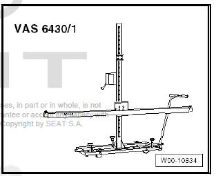
- Setting device - VAS 6430-
- or adjustment system, basic set - VAS 6430/1-
- ACC reflector panel - VAS 6430/3-
- Wheel alignment computer
Note
- Before driving vehicle onto wheel alignment platform, make sure there is sufficient space between vehicle and setting device - VAS 6430- . The distance between setting device - VAS 6430/3- and the sensor must be 120 cm +- 2.5 cm.
- If the available space is not adequate, move the vehicle backwards onto the axle measurement platform in order to be able to use a corresponding space.
- If position of ACC reflector mirror - VAS 6430/3- on alignment beam is changed, setting of ACC setting device - VAS 6430- must always be checked (e.g. spirit levels, individual toe values on adjusting beam, etc.).
- Before calibrating, read out event memory and rectify faults as necessary.
Adjustment procedure described here is based on setting device - VAS 6430- .
The following setting sequence is to be adhered to:
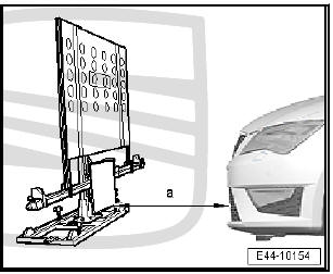
- - Establish a distance of 120 cm +- 2.5 cm between the centrally fitted ACC reflective mirror - VAS 6430/3- and the sensor in the air intake grille.
- - Install the ACC reflecting mirror - VAS 6430/3- centrally on the alignment beam.
- - Calibrate the adaptive cruise control unit - J428- .
If wheel alignment has just been carried out, the steps described under "Setting without preceding wheel alignment" do not have to be carried out.
Setting without preceding wheel alignment
- Press button to select ACC calibration in wheel alignment computer.
- Note testing preconditions for wheel alignment.
- Drive car onto wheel alignment platform.
- Connect battery charger.
- Connect - Vehicle diagnostic tester. (Route diagnostic cable through open window.)
Note During the calibration, make sure that all doors are closed on the vehicle and that the exterior lights are switched off.
- Bring wheels into straight-ahead position.
- Attach quick-release clamps to rear wheels.
- Attach rear wheel alignment sensors.
- Carry out wheel rim run out compensation for rear wheels.
Setting with or without preceding wheel alignment
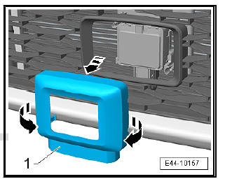
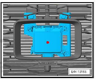
- Remove the trim-1-.
- Remove dirt, if there is any, from the sensor lens.
- Set adjustment screws.
Note Note different designs.
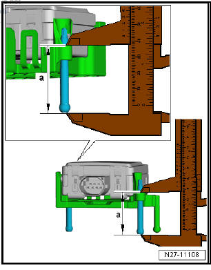
- Position ACC setting device - VAS 6430/3- centrally and parallel at a distance -a- from centrally fitted ACC reflector mirror - VAS 6430/3- to adaptive cruise control unit - J428- .
a - 120 cm + 2.5 cm
Note ACC setting device - VAS 6430- is not allowed to be moved on alignment beam.
Sequence of steps for all
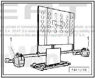
- Mount measurement transducers -1- of front wheels on alignment beam.
- In zone -A- set the position -2- on the rotary control to cover the marker on the mirror (Number 2 of the rotary control must point towards the vehicle).
- Use the adjusting screws -1-, -2- and -3- to bring spirit levels -A- and -B- on - VAS 6430/3- horizontal.
- Adjust mirror -4- by means of crank handle -arrow- in such a way that the laser beam hits the sensor lens in the middle.
- Position the mirror on side of the alignment beam so that the laser beam contacts the centre of the sensor lens.
- Use adjusting screw -1- to level spirit level -2-.
- Turn fine adjuster screw -5- until display on wheel alignment computer is within tolerance.
- Use adjusting screw -1- to level spirit level -2-.
- Now, use laser beam -3- of -VAS 6430/3- to check again whether spirit levels are horizontal and laser beam hits centre of sensor lens.
Note If the laser beam does not hit the mirror the alignment of the -VAS 6430/3- must be repeated once again.
The subsequent steps are performed via the vehicle diagnostic tester "in Guided Fault Finding":
VAS PC
Vehicle diagnostic tester is connected.
- Select operating mode Guided fault finding .
- Select the Go to key as well as the function "Function / Component
Selection"in order to follow the following structure:
- Suspension
- 13 - Proximity control
- 01 - Systems capable of diagnosis
- 13 - Distance control -J428
- 13 - Control unit for the distance control; functions
- 13 - Calibration
ODIS - Off-board Diagnostic Information System
Vehicle diagnostic tester is connected.
- Select mode Diagnosis and start the diagnosis.
- Select tab Test plan .
- Select Self test key to follow the following structure:
- Suspension
- 13 - Proximity control
- 01 - Systems capable of diagnosis
- 13 - Distance control -J428
- 13 - Control unit for the distance control; functions
- 13 - Calibration
Follow instructions on screen to perform calibration.
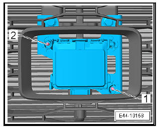
- For alignment of the distance control unit - J428- the adjusting tool - VAS 6190/2- is to be used.
Designation of adjusting screws of adaptive cruise control unit - J428-
- - Setting screw 1
- - Setting screw 2
| WARNING ACC adjustment is not completed until - Vehicle diagnostic tester displays "Final control element diagnosis ended". |
 Matching wheels and tyres
General information
When radial or lateral runout of the wheel and tyre coincide, the
imbalance of the wheel is amplified by the tyre.
For technical reasons, 100% true running is not possible.
B ...
 Front camera for driver assist systems
Calibrating front camera for driver assist
systems
Note
The following situations can cause the camera function to be impaired
by sustained poor visibility of the lane marker lines:
Camera visi ...
See also:
Removing and installing electromechanical
parking brake button - E538- /
auto-hold button - E540-
Removing
Remove centre console cover.
Unlock the retaining clips -arrows- and remove the button -1-
from its retainer.
Installing
Installation is carried out in the reverse sequence; note ...
