Seat Leon >> Front camera for driver assist systems
Calibrating front camera for driver assist systems
Note The following situations can cause the camera function to be impaired by sustained poor visibility of the lane marker lines:
- Camera vision is obstructed by dirt or ice, etc. This should be rectified accordingly.
- The field of view of the camera is fogged over.
The camera aperture must be cleaned manually if there is heavy contamination on the inside of the windscreen in the field of view of the camera. To do this, the control unit and lens hood must be removed and the windscreen cleaned using cleaning solution.
Remove control unit and lens hood.
Correct calibration is a basic precondition for the driver assistance system's Front camera for driver assistance systems - R242- .
The front camera for driver assist systems - R242- must be recalibrated if:
- "No or incorrect basic setting/adaptation" entry stored in the event memory.
- The driver assistance system's front camera - R242- was replaced.
- Windscreen has been renewed or removed.
- Rear axle toe setting has been adjusted.
- Modifications have been made to the car's running gear that have an effect on the body height.
- Vehicle level senders are re-taught in vehicles with damping control.
Note
- Before calibrating the driver assistance system's front camera, read out event memory and rectify faults as necessary.
- Calibration of the driver assistant system's front camera is only permitted using wheel alignment unit authorised by SEAT!
- Calibration of the driver assistant system's front camera is only permitted using the setting device - VAS 6430- !
Special tools and workshop equipment required
- Adjustment aid - VAS 6430-
- Wheel alignment computer
- Vehicle diagnostic tester
Note
- The driver assistance system's front camera - R242- must be correctly located in the holder.
- The field of view of the camera must be clean and clear.
- Before driving the vehicle onto the wheel alignment platform, make sure there is sufficient space between the midpoint of the hub of the front wheels and the setting device - VAS 6430- .
- The distance between the setting device - VAS 6430- and the centre point of the hub of the front wheels must be 1500 mm +- 25 mm.
- If the available space is not adequate, move the vehicle backwards onto the axle measurement platform in order to be able to use a corresponding space.
- The calibration board must be positioned centrally on the setting device.
- The event memory must be read before starting calibration.
Any memory entries must be deleted.
- Note testing preconditions for wheel alignment .
- Drive car onto wheel alignment platform.
- Connect battery charger .
- Connect - Vehicle diagnostic tester. (Route diagnostic cable through open window.)
Note
During the calibration procedure, make sure that all the car doors remain closed and that the car's outside lighting is switched off.
- Bring wheels into straight-ahead position.
- Select calibration sequence for the front camera - R242- in the wheel alignment computer.
- Mount quick-release clamps on all four wheels.
- Mount measuring transducers on wheels.
- Carry out wheel rim run out compensation for rear wheels.
- Bounce springs.
- Measure standing height at all four wheels and note it.
Note
- Setting device - VAS 6430- is not allowed to be moved on alignment beam.
- For the next step the wheel alignment platform must be set at the lowest available position.
- Turn setting device - VAS 6430- upwards so that alignment beam is parallel to middle of measurement transducers on front wheels, in order to perform a correct measurement with distance measuring unit -1-.
- - Distance measuring unit with tape measure and socket pin
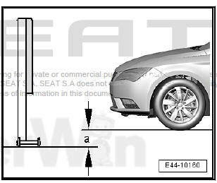
- Position setting device - VAS 6430- at distance -a- of 1,500 mm +- 25 mm from centre point of hub of front wheels to beam of setting device - VAS 6430- .
Caution
|
- Mount measurement transducer -1- of front wheels onto setting device - VAS 6430- .
- Measure height value -a- between standing surface of setting device - VAS 6430- and wheel support surface on wheel alignment platform. Enter value in wheel alignment computer.
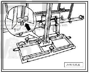
- Unscrew clamping bolt -arrow-, place measuring bar -1- on floor.
- Setting the calibration table - VAS 6430/4- with the hand wheel -1- to the target height -2-, pursuant to the information in the axle alignment computer (1200 mm + height difference -a-), and note.
When nominal height has been reached, measuring bar -1- must be moved upwards slightly and secured with clamping screw -arrow-.
- Move setting device - VAS 6430- sideways -arrows B- until display on wheel alignment computer is within tolerance.
- Screw down adjuster screws -2- and -3- slightly to secure setting device - VAS 6430- against rolling away.
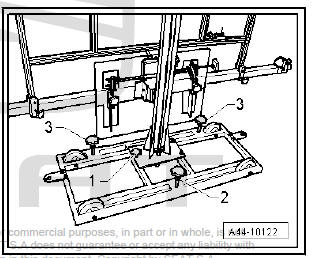
- Turn fine adjuster screw -1- until display on wheel alignment computer is within tolerance.
- Set spirit level -A- to horizontal position with adjuster screw -1-.
- Use adjuster screws -2- and -3- to level spirit level -B-.
- Unscrew clamping bolt -arrow-, place measuring bar -1- on floor.
- Check nominal height -2- again and correct if necessary.
When nominal height has been reached, measuring bar -1- must be moved upwards slightly and secured with clamping screw -arrow-.
Concluding work is carried out via - Vehicle diagnostic tester.
- Switch on ignition.
- On - Vehicle diagnostic tester, select "Guided Fault Finding".
Bodywork (Repair group 01, 27, 50...97)
Electric systems (Repair groups 01;27;90...97)
01_Self-diagnosis capable systems
Front camera for driver assistance system -R242-
Camera for driver assistance systems, functions
A5 - Calibrating the control unit
Follow instructions on screen to perform calibration.
Note The next step in Guided fault finding is to measure the body height.
- Enter the noted standing height.
 Adaptive cruise control
Calibrating adaptive cruise control
Calibrating Adaptive Cruise Control
(ACC)
Before calibrating the adaptive cruise control (ACC), it must be
ensured that the sensor, the retainers and the fixing ...
 Steering
...
See also:
Manual gearbox
Driving a car with a manual gearbox
Fig. 116 Detail of the
centre console: Shift
diagram of a 5-speed
manual gearbox
Fig. 117 Detail of the
centre console: Shift
diagram of a 6-speed
manua ...
