Seat Leon >> Dismantling and assembling drive shaft
Dismantling and assembling drive shaft, constant velocity joint VL100
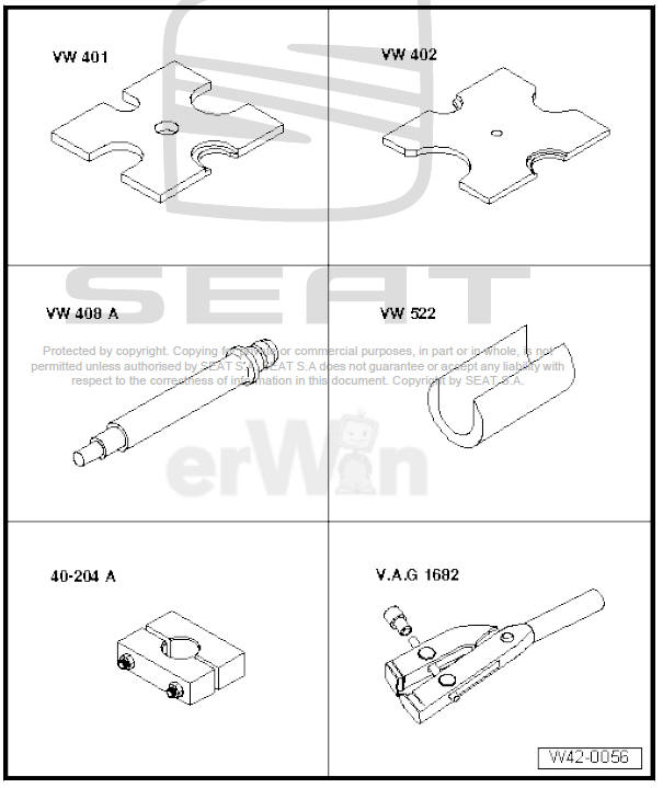
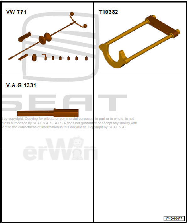
Special tools and workshop equipment required
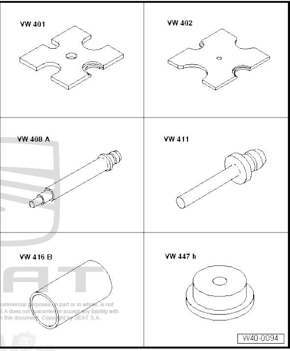
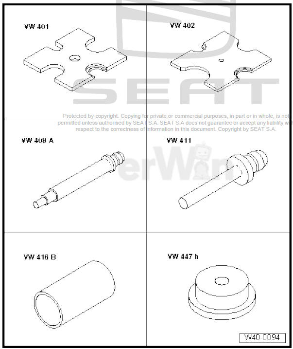
- Tightening plate - VW 401-
- Tightening plate - VW 402-
- Die - VW 408 A-
- Die - VW 411-
- Tube element - VW 416 B-
- Thrust pad - VW 447 H-
- Pliers - VW 161 A-
- Torque wrenches - V.A.G 1331-
- Torque wrenches - V.A.G 1332-
- Clamp tensioner - V.A.G 1682-
- attachment tool - T10065-
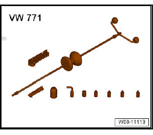
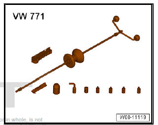
- Universal tool - VW 771-
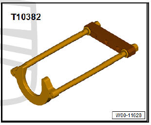
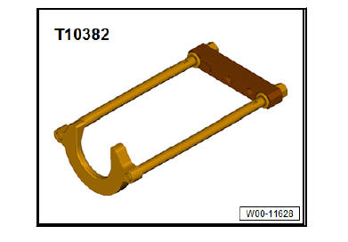
- Puller - T10382-
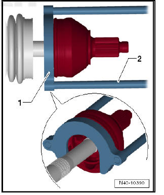
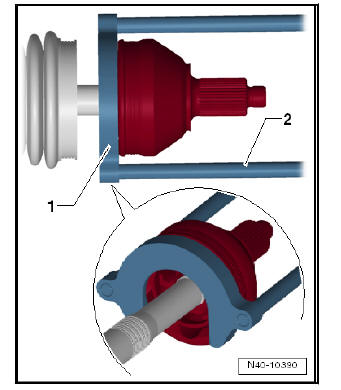
Removing the dustguard for exterior constant velocity joint
- Clamp drive shaft in vice using protective jaw covers.
- Push the dust guard backwards.
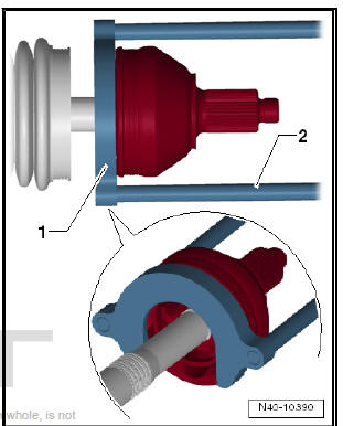
- Set puller - T10382- up so that smooth side of puller plate - T10382/1- points to spindles - T10382/2- .
- Assemble puller - T10382- complete with multi-purpose tool - VW 771- .
- Pull constant velocity joint from drive shaft with puller - T10382- and multi-purpose tool - VW 771- .
- - Holding plate - T10382/1-
- - Spindles - T10382/2-
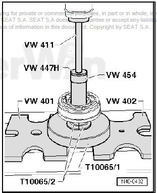
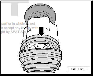
Driving on outer constant velocity joint
Installation position of dished spring and thrust washer on outer joint
- - Dished spring
- - Thrust washer
- Install new retaining ring.
- If necessary, push new joint boot onto drive shaft.
- Knock onto shaft with plastic hammer until circlip engages.
Pressing off inner constant velocity joint
Assembling
Installation position of the plate spring on the joint
1 - Dished spring
Pressing on inner constant velocity joint
Note Chamfer on internal circumference of ball hub (splines) must face contact shoulder on drive shaft.
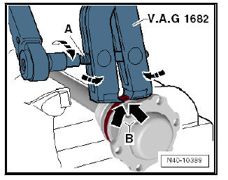
Clamp clip on outer joint
- Apply clamp tensioner - V.A.G 1682- as illustrated. Ensure jaws of tensioner lie in corners -arrows B- of clamp.
- Tighten hose clip by turning spindle with torque wrench (take care to keep clamp tensioner straight).
Note
- Due to the hard material of the protective boot (compared to rubber) and the necessity of using a stainless steel clamp, it is only possible to tension the clamp with clamp tensioner - V.A.G 1682- .
- Tightening torque: 25 Nm.
- Use a torque wrench -C- with a range between 5 ... 50 Nm (e.g torque wrench - V.A.G 1331- ).
- Check that the spindle thread -A- of the pliers is easily movable.
Apply MOS 2 grease if necessary.
- If the thread is tight (e.g. due to dirt), the required clamping force for the clamp will not be attained although the specified tightening torque is applied.
Tightening clamp on small diameter
Dismantling and assembling drive shaft, constant velocity joint VL107
Special tools and workshop equipment required
- Tightening plate - VW 401-
- Tightening plate - VW 402-
- Die - VW 408 A-
- Support sleeve - VW 522-
- Tensioner - 40 - 204 A-
- Clamp tensioner - V.A.G 1682-
- Universal tool - VW 771-
- Puller - T10382-
- Torque wrenches - V.A.G 1331-
Removing the dustguard for exterior constant velocity joint
- Clamp drive shaft in vice using protective jaw covers.
- Push the dust guard backwards.
- Set puller - T10382- up so that smooth side of puller plate - T10382/1- points to spindles - T10382/2- .
- Assemble puller - T10382- complete with multi-purpose tool - VW 771- .
- Pull constant velocity joint from drive shaft with puller - T10382- and multi-purpose tool - VW 771- .
- - Holding plate - T10382/1-
- - Spindles - T10382/2-
Driving on outer constant velocity joint
- Install new retaining ring.
- If necessary, push new joint boot onto drive shaft.
- Knock onto shaft with plastic hammer until circlip engages.
Separate cover for inner constant velocity joint
- Remove circlip.
- Remove both tightening clamps and move the dustguard towards the exterior joint.
- Separate the dustguard with a punch.
Pressing off inner constant velocity joint
Assembling
Pressing on inner constant velocity joint
- Insert the constant velocity joint up to the limit.
- Install retaining ring.
- Coat sealing surface of cover with -D 454 300 A2- .
- Apply continuous bead of sealant with Ø 2...3 mm past inner edge of holes -arrow- to clean surface of cover.
- Align the new cover with its bolts -arrows- with the corresponding holes.
The alignment must be very accurate, because no further alignment is possible once the part has been hammered on.
- Drive on cover using a plastic hammer.
- Wipe off any excess sealant.
Clamp clip on outer joint
- Apply special pliers -V.A.G 1682- as shown in diagram. Ensure jaws of tensioner lie in corners -arrows B- of clamp.
- Tighten hose clip by turning spindle with torque wrench (take care to keep clamp tensioner straight).
Note
- Due to the hard material of the protective boot (compared to rubber) and the necessity of using a stainless steel clamp, it is only possible to tension the clamp with clamp tensioner - V.A.G 1682- .
- Tightening torque: 25 Nm.
- Use a torque wrench -C- with a range between 5 ... 50 Nm (e.g torque wrench - V.A.G 1331- ).
- Check that the spindle thread -A- of the pliers is easily movable.
Apply MOS 2 grease if necessary.
- If the thread is tight (e.g. due to dirt), the required clamping force for the clamp will not be attained although the specified tightening torque is applied.
Tightening clamp on small diameter
Checking outer constant velocity joint
Checking inner constant velocity joint
Checking function of constant velocity joint
Dismantling and assembling drive shaft, triple roller joint AAR
Special tools and workshop equipment required
- Tightening plate - VW 401-
- Tightening plate - VW 402-
- Die - VW 408 A-
- Die - VW 411-
- Tube element - VW 416 B-
- Thrust pad - VW 447 H-
- Pliers for clamps - V.A.G 1275-
- Torque wrenches - V.A.G 1331-
- Torque wrenches - V.A.G 1332-
- Clamp tensioner - V.A.G 1682-
- attachment tool - T10065-
- Universal tool - VW 771-
- Puller - T10382-
Removing the dustguard for exterior constant velocity joint
- Clamp drive shaft in vice using protective jaw covers.
- Push the dust guard backwards.
- Set puller - T10382- up so that smooth side of puller plate - T10382/1- points to spindles - T10382/2- .
- Assemble puller - T10382- complete with multi-purpose tool - VW 771- .
- Pull constant velocity joint from drive shaft with puller - T10382- and multi-purpose tool - VW 771- .
- Holding plate - T10382/1-
- Spindles - T10382/2-
Driving on outer constant velocity joint
- Install new retaining ring.
- If necessary, push new joint boot onto drive shaft.
- Knock onto shaft with plastic hammer until circlip engages.
Dismantling triple roller joint
- Clamp drive shaft in vice using protective jaw covers.
- Open the inner joint clamps and push the joint dust guard backwards.
- Pull joint body off drive shaft.
- Remove circlip.
1 - Pliers (commercially available)
- or -VW 161 A- - Set drive shaft into press.
- Press triple roller star off drive shaft.
- Pull boot off shaft.
- Clean shaft, joint body and groove for seal.
Assembling triple roller joint
- Push small hose clip for boot onto shaft.
- Push joint boot onto shaft.
Fitting triple roller star
Chamfer on triple roller star -arrow- faces towards shaft and serves as an assembly aid.
- Fit triple roller spider on shaft and press on as far as stop.
- Ensure that pressure does not exceed 3.0 t.
- If necessary, coat splines of drive shafts and triple roller star with lubricating paste - G 052 142 A2- .
- Insert retaining ring, ensuring that it is seated correctly.
- Press half of total amount of grease from repair kit into triple roller joint.
- Place boot adapter onto joint.
- Slide joint body over rollers and hold.
- Press remaining amount of grease from repair kit into rear of triple roller joint.
- Slide boot onto boot adapter and ensure that boot engages correctly in groove -arrow- of adapter.
- Install hose clip.
Note Clamping lug of clamp -arrow A- must be located between securing flanges of joint body -arrows B-. This is the only way of assuring that the multi-point socket head bolts can be guided correctly when installing the drive shaft.
Tightening clamp on large diameter of inner joint
- Position clamp tensioner - V.A.G 1682- as shown in illustration.
Ensure jaws of tensioner lie in corners -arrows B- of clamp.
- Tighten hose clip by turning spindle with torque wrench (take care to keep clamp tensioner straight).
Note
- Due to the hard material of the protective boot (compared to rubber) and the necessity of using a stainless steel clamp, it is only possible to tension the clamp with clamp tensioner - V.A.G 1682- .
- Tightening torque: 25 Nm.
- Use torque wrench -C- with adjustment range 5 ... 50 Nm, (e.g. torque wrench - V.A.G 1331- ).
- Check that the spindle thread -A- of the pliers is easily movable.
Apply MOS 2 grease if necessary.
- If the thread is tight (e.g. due to dirt), the required clamping force for the clamp will not be attained although the specified tightening torque is applied
Clamp clip on outer joint
- Apply clamp tensioner - V.A.G 1682- as illustrated. Ensure jaws of tensioner lie in corners -arrows B- of clamp.
- Tighten hose clip by turning spindle with torque wrench (take care to keep clamp tensioner straight).
Tightening clamp on small diameter of inner/outer joint
 Loosening and tightening drive shaft
bolt
Loosening and tightening drive shaft
bolt
Special tools and workshop equipment required
Socket, AF 24 - T10361 A
Digital Torque wrench - VAG 1756A-
CautionWheel bearings must not be subjected to load
after loosenin ...
 Checking outer constant velocity joint
The joint is to be dismantled to renew the grease if it is heavily
soiled, or to check the running surfaces of the balls for wear and
damage.
Removing
Before dismantling, mark position of ball ...
See also:
Content
This manual is structured to give you the information you need as quickly and
clearly as possible. The contents of this Manual are grouped into relatively
short sections making up chapters (e.g. “ ...
