Seat Leon >> Removing and installing subframe with steering box
Removing and installing subframe with steering box, LHD
Special tools and workshop equipment required
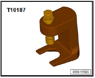
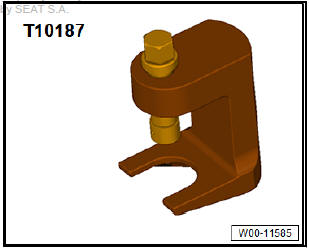
- Ball joint puller - T10187-
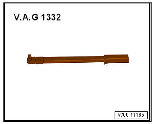
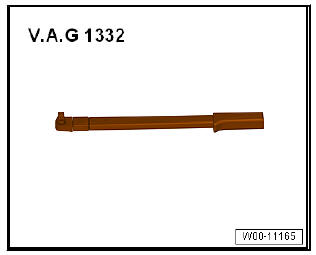
- Torque wrenches - V.A.G 1332-
Removing
- To prevent unintentional turning, secure steering wheel in straight-ahead position with adhesive tape -arrow-.
Note
- Only use adhesive tape that can be completely removed afterwards without leaving marks.
- Do not turn steering wheel while performing repair work, as otherwise airbag coil connector and return ring with slip ring - F138- could be damaged.
- Pull out the ignition key to lock the steering wheel.
Vehicles with keyless locking and starting system "Keyless Access"
- Switch off ignition and open driver's door so that the steering lock engages.
Continuation for all models:
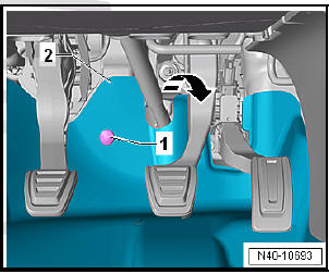
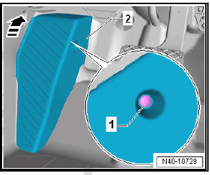
- Unscrew bolts -1- and fold footwell trim -2- in -direction of arrow- into the vehicle interior.
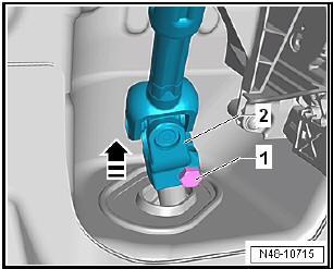
- Unscrew bolt -1- from universal joint -2- and pull off universal joint in -direction of arrow-.
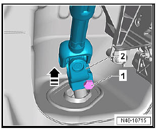
| Caution The following work must not be performed while the universal joint is separated from the steering rack:
Not adhering to these instructions will result in irreparable damage. |
- Remove front wheels.
- Remove lower noise insulation.
For vehicles with natural gas engines
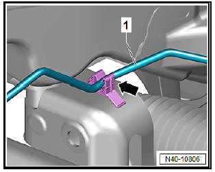
- Detach natural gas line -1- from clip -arrow-.
Continuation for all models:
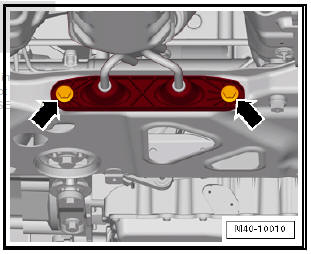
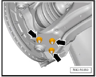
- Detach exhaust system bracket from subframe -arrows-.
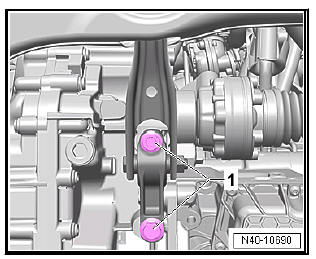
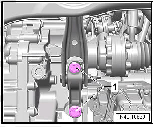
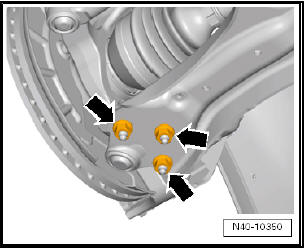
- Remove bolts -1- for pendulum support.
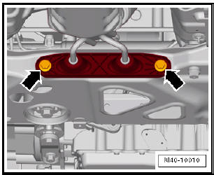
- Remove nuts -arrows- on both sides of vehicle.
- Pull swivel joint out of suspension link.
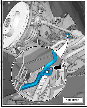
- Remove nut -1- from coupling rod -3- (left and right sides).
- Pull out coupling rod -3- from anti-roll bar -2- on left and right side.
- Loosen nut on track rod ball joint but do not remove completely.
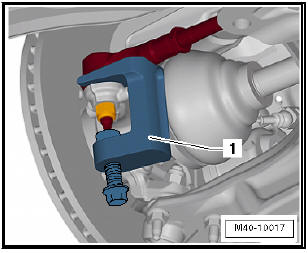
- Using ball joint puller - T10187- -1-, press track rod ball joint off wheel bearing housing, and unscrew nut.
| Caution Leave nut screwed several turns onto track rod ball joint shank to protect thread. |
Vehicles with vehicle level senders
- Disconnect connector -1- on front left vehicle level sender - G78- and/or front right vehicle level sender - G289- , as applicable.
Continuation for all models:
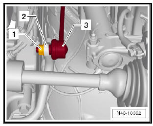
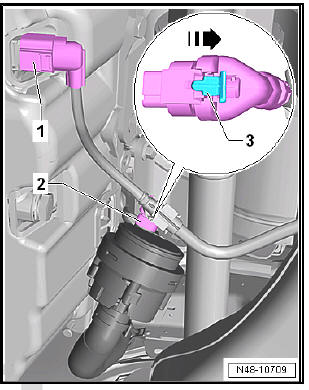
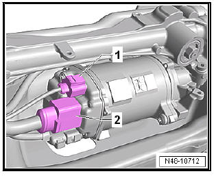
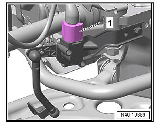
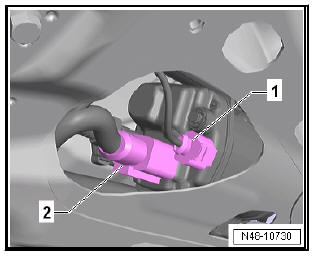
- Disconnect connector -1- of the oil level and oil temperature sender - G266- .
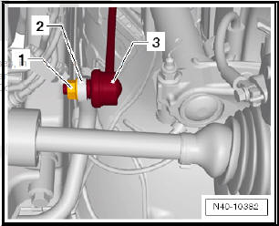
- If installed, disconnect the connector -2- from the heating support pump - V488- . Open locking mechanism -3- in -direction of arrow-, and release connector.
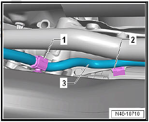
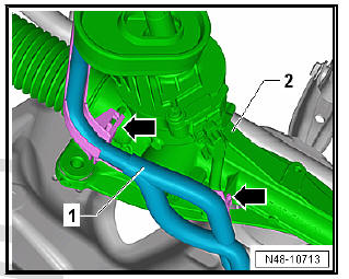
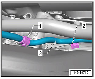
- Pull clips -1- and -2- off of the wiring harness -3- of the assembly carrier and of the steering rack.
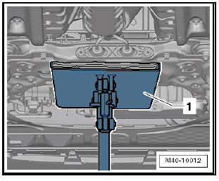
- Position engine and gearbox jack - V.A.G 1383 A- -1- under subframe.
- Fixing subframe and lowering approx. 10 cm.
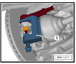
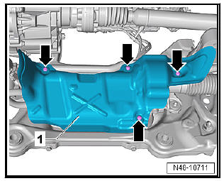
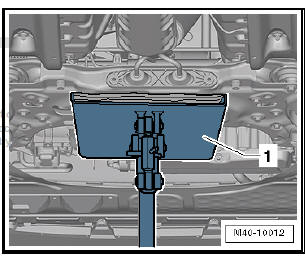
- Unscrew bolts -arrows- and remove heat shield -1- from steering box.
Note Different heat shields -1- are installed depending on the engine.
On some engines it is possible to access the connectors for the steering rack without removing the heat shield.
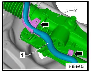
- Disconnect connectors -1- and -2- from steering rack.
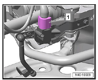
- Unclip wiring harness -1- from steering box -2- -arrows-.
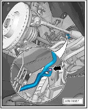
- Pull out spreader clip -arrow-.
- Lower subframe with engine and gearbox jack - V.A.G 1383 A- .
- Secure subframe to engine and gearbox jack - V.A.G 1383 Awith the appropriate strap.
Installing
Carry out installation in the reverse sequence, noting the following:
Note
- Coat seal on steering box with suitable lubricant, e.g. soft soap, before installing steering box.
- After fitting the steering box to the universal joint ensure that
the seal is not kinked against the assembly plate on the steering
box. The opening to the footwell must seal correctly.
Otherwise, noise or water may enter.
- Ensure sealing surfaces are clean.
- On vehicles with vehicle level sender, carry out basic settings for wheel damper electronics - Vehicle diagnostic tester
Specified torques
- Bolts for pendulum support .
- Bolts for noise insulation .
- Exhaust pipes double clamp.
If even when using locating pins - T10486/1- a crooked steering wheel is determined during the road test, carry out a wheel alignment check. In this case the wheel alignment test results must be archived in the vehicle files.
Removing and installing subframe with steering box, RHD
Special tools and workshop equipment required
- Ball joint puller - T10187-
- Torque wrenches - V.A.G 1332-
Removing
- To prevent unintentional turning, secure steering wheel in straight-ahead position with adhesive tape -arrow-.
Note
- Only use adhesive tape that can be completely removed afterwards without leaving marks.
- Do not turn steering wheel while performing repair work, as otherwise airbag coil connector and return ring with slip ring - F138- could be damaged.
- Pull out the ignition key to lock the steering wheel.
Vehicles with keyless locking and starting system "Keyless Access"
- Switch off ignition and open driver's door so that the steering lock engages.
Continuation for all models:
- Unscrew bolt -1-.
- Push foot support -2- upwards in -direction of arrow- and remove.
- Fold floor covering to the rear.
- Unscrew bolt -1- from universal joint -2- and pull off universal joint in -direction of arrow-.
| Caution The following work must not be performed while the universal joint is separated from the steering rack:
Not adhering to these instructions will result in irreparable damage. |
- Remove front wheels.
- Remove lower ground protection.
For vehicles with natural gas engines
- Detach natural gas line -1- from clip -arrow-.

Continuation for all models:
- Detach exhaust system bracket from subframe -arrows-.
- Remove bolts -1- for pendulum support.
- Remove nut -1- from coupling rod -3- (left and right sides).
- Pull out coupling rod -3- from anti-roll bar -2- on left and right side.
- Remove nuts -arrows- on both sides of vehicle.
- Pull swivel joint out of suspension link.
- Loosen nut on track rod ball joint but do not remove completely.
- Using ball joint puller - T10187- -1-, press track rod ball joint off wheel bearing housing, and unscrew nut.
| Caution Loosen the bolt by a couple of turns and leave on the ball joint to protect the thread. |
Vehicles with vehicle level senders
- Disconnect connector -1- on front left vehicle level sender - G78- and/or front right vehicle level sender - G289- , as applicable.
Continuation for all models:
- Disconnect connector -1- of the oil level and oil temperature sender - G266- .
- If installed, disconnect the connector -2- from the heating support pump - V488- . Open locking mechanism -3- in -direction of arrow-, and release connector.

- Pull wiring harness -3- clips -1- and -2- off subframe and steering box.
- Position engine and gearbox jack - V.A.G 1383 A- -1- under subframe.
- Fixing subframe and lowering approx. 10 cm.
- Disconnect connectors -1- and -2- from steering rack.
- Unclip wiring harness -1- from steering box -2- -arrows-.
- Pull out spreader clip -arrow-.
- Lower subframe with engine and gearbox jack - V.A.G 1383 A- .
- Secure subframe to engine and gearbox jack - V.A.G 1383 Awith the appropriate strap.
Installing
Carry out installation in the reverse sequence, noting the following:
Note
- Coat seal on steering box with suitable lubricant, e.g. soft soap, before installing steering box.
- After fitting the steering box to the universal joint ensure that
the seal is not kinked against the assembly plate on the steering
box. The opening to the footwell must seal correctly.
Otherwise, noise or water may enter.
- Ensure sealing surfaces are clean.
- On vehicles with vehicle level sender, carry out basic settings for wheel damper electronics - Vehicle diagnostic tester
Specified torques
- Bolts for pendulum support .
- Bolts for noise insulation .
- Exhaust pipes double clamp .
If even when using locating pins - T10486/1- a crooked steering wheel is determined during the road test, carry out a wheel alignment check. In this case the wheel alignment test results must be archived in the vehicle files.
 Removing and installing subframe without
steering box
Removing and installing subframe without
steering box
Special tools and workshop equipment required
Torque wrenches - V.A.G 1332-
Engine elevator - V.A.G 1383 A-
Removing
Note
The subframe is removed together with the suspension links. ...
 Repairing subframe
Special tools and workshop
equipment required
attachment tool - T10205-
Torque wrenches - V.A.G
1332-
Hydraulic press - VAS
6178-
Foot pump - VAS 6179-
attachment tool - VAS
6779-
...
See also:
Removing and installing brake splash
plate
Removing:
Dismantle brake disc.
Unscrew screws -arrows- of splash plate -1-.
Remove splash plate -1- from the wheel hub.
Installation:
Clean wheel hub and splash plate.
Fit splash pla ...
