Seat Leon >> Disassembly and assembly of the input shaft
Special tools and workshop equipment required
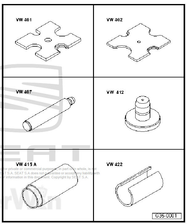
- Tightening plate - VW 401-
- Tightening plate - VW 402-
- Die - VW 407-
- Die - VW 412-
- Tube element - VW 415 A-
- Tube element - VW 422-
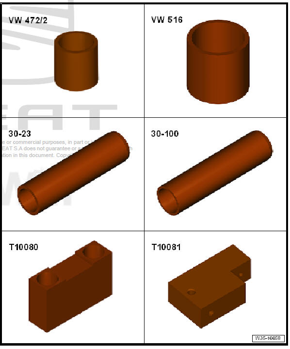
- Spacer sleeve - VW 472/2-
- Tube element - VW 516-
- Extension - 30-23-
- Inlay socket - 30-100-
- Thrust pad - T10080-
- Thrust pad - T10081-
- Thrust block - T10083-
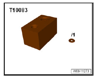
- Plate - T10083/1-
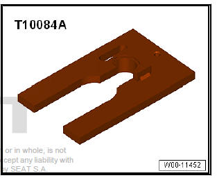
- Tightening plate - T10084 A-
- Removal pliers - VW 161 A-
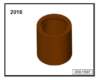
- Tube element - 2010-
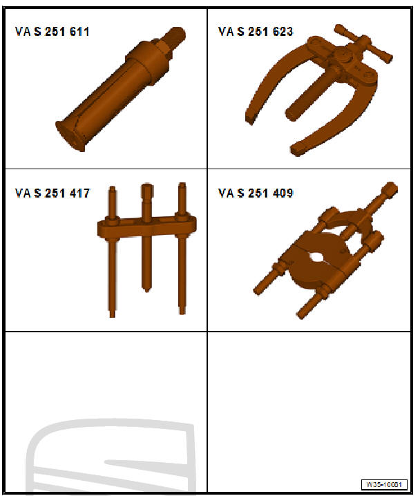
- Internal puller - VAS 251 611- or, e.g. internal puller - Kukko 21/5-
- Counter-support - VAS 251 623- or, e.g. counter-support - Kukko 22/2-
- Puller - VAS 251 417- , or e.g. puller - Kukko 18/1-
- Splitter - VAS 251 409- , or e.g. splitter - Kukko 17/1-
- Removal pliers - VW 161 A-
- -Calibre-
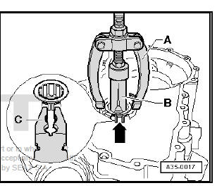
Pulling cylindrical roller bearing out of clutch housing
- When pulling out, squeeze together retaining ring -arrow- of cylindrical roller bearing, using pliers -C-.
- - Counter-support - VAS 251 623- or, e.g. counter-support - Kukko 22/2-
- - Internal puller - VAS 251 611- or, e.g. internal puller - Kukko 21/5-
Extract the roller bearing from the clutch housing
- Support gearbox housing with tube - VW 415 A- (not visible in figure) directly below bearing support.
- When pressing in, compress circlip -arrow- for roller bearing using pliers -A-.
- Remove the pliers before the bearing is in its final installation position. The securing ring should insert into the groove of the clutch pan.
Detach the allotment with grooved ball bearings
- Slide locking collar for 1st and 2ndgear onto 2ndgear.
- Then slide pressure plate - T10084/A- onto input shaft to stop from side.
- Feed the centring pins of the tool - T10081- through the holes on the input and output shafts.
Releasing
Cylindrical roller bearing inner race together with: thrust washer, 4th gear synchromeshed gear with needle bearing, locking collar/ synchro-hub for 3rd and 4th gear and 3rd gear synchromeshed gear
- First remove retaining ring with Circlip pliers - VW 161 A- .
The inner bearing races of roller bearings too can only be removed individually together with the 4th gear selector gear
- First remove retaining ring with Circlip pliers - VW 161 A- .
- Position splitter -B- behind teeth of synchromeshed gear for 4th gear which engage in the other gear wheel (not dog teeth) and tension.
- - Puller - VAS 251 417- , or e.g. puller - Kukko 18/1-
- - Splitter 12...75 mm - VAS 251 409- , or e.g. splitter - Kukko 17/1-
- - Protection gags
Dismantling and assembling 3rd and 4th gear locking collar and synchro-hub
- - Spring
- - Mobile element
- - Synchromesh hub
- - Locking element
- The locking collar is fitted onto the synchro-hub.
Deepest notches -arrow A- for locking pieces in synchro-hub and notches -arrow B- in locking collar must align.
Assembling locking collar and synchro-hub for 3rd and 4th gears
- Locking collar has been pushed over synchro hub.
- Fit the locking elements in the deepest grooves -arrows- and fit the elastic rings off-set by 120º. Angled end of spring must locate in hollow locking piece.
Installation position locking collar/synchronising hub 3rd and 4th gear
If present, the groove on the front edge -arrow- should point towards 4th gear.
The high collar points towards 3rd gear.
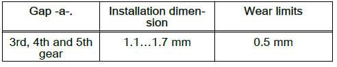
Checking synchro-ring for wear
- Press synchro-ring onto cone of synchromeshed gear and measure gap -a- using feeler gauge.
- Measure distance -a- at three points offset by approx. 120º with a feeler gauge.
- Make a note of average value.
Pressing on synchro-hub with locking collar for 3rd and 4th gears
If present, the groove on the front edge of the locking collar points towards 4th gear.
The high shoulder of the synchro-hub points towards 3rd gear.

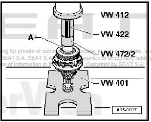
Pressing on sleeve -A- for 4th gear needle bearing
- After pressing on sleeve -A-, fit 4th gear needle bearing, 4th gear synchro-ring with synchromeshed gear and thrust washer.
Insert the inner ring -A- of the cylindrical roller bearing
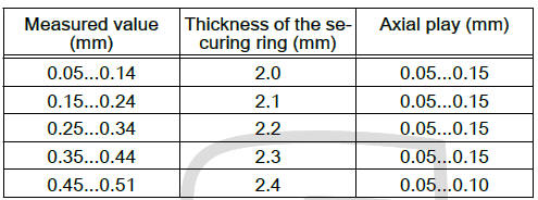
Determining thickness of retaining ring
- Insert a 2.0 mm thick retaining ring -A- in groove of input shaft and press upwards -arrow-.
- Using a thickness gauge -C-, measure the distance between the inner ring -B- and the fitted securing ring -A-.
- Remove retaining ring used for measuring purposes.
- Select the securing ring using the table.
Note Allocate retaining rings using Electronic parts catalogue (ETKA).
Available retaining rings
Pressing the bearing support with grooved ball bearings onto the drive and output shaft.
Note
- The input shafts of the different gearboxes have different lengths as the dimension of the splines - dimension -a- - are different (the figure shows the shaft mounted).
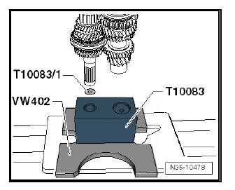
- To ensure that bearing support is always evenly pressed onto shafts, it is necessary for shafts always to be inserted evenly into thrust block - T10083- .
- If necessary, insert a shim - T10083/1- (3 mm thick) into fitting hole for input shaft.
- For this person, dimension -a- of the secondary shaft splines has to be measured.
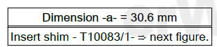
Fit shim - T10083/1- .
Adapt the bearing mount
- Before adapting, heat the allotment to about 100 ºC.
| WARNING Use protective gloves! |
Pressing on sleeve -A- for 5th gear needle bearing
Removing stop ring
- Unclip hook -A- of the check ring from the synchro-hub using a screwdriver.
Dismantling and assembling 5th gear locking collar and synchrohub
- - Spring
- - Locking element
- - Synchro-hub installation position: groove on face -arrow A- and wide shoulder -arrow B- must face 5th gear.
- - Mobile element
- - Stop ring
- The locking collar is fitted onto the synchro-hub.
Deeper notches -arrow C- for locking pieces in synchro-hub and notches -arrow D- in locking collar must align.
Assembling 5th gear locking collar/synchro-hub
- Locking collar has been pushed over synchro hub.
- Fit the locking elements in the deepest grooves -arrows- and fit the elastic rings off-set by 120º. Angled end of spring must locate in hollow locking piece.
Install stop ring.
- Press on stop ring using tube - 2010- .
- Insert stop ring together with tube - 2010- into 5th gear synchro- hub/locking collar (observe installation position).
The hooks -arrow 1- lock in the recess -arrow 2- of the synchrohub locking pieces.
- Press stop ring downwards until hooks engage.
 Assembly overview - input shaft
Note
When installing new sliding gears or a new input shaft, all details
of the - Electronic parts catalogue ETKA
and technical data must be observed.
Install all bearings, synchromeshed ge ...
 Input shaft oil seal: replacement
Special tools and workshop equipment required
Pressing-off lever - T20143/1-
Thrust pad - T40008-
Sealing grease
For grease allocation, refer to - Electronic parts catalogue
(E ...
See also:
Using these instructions
The vehicle includes a multifunction module from where it is possible to
control the audio, telephone and radio / navigation functions and the automatic
gearbox* without needing to distract the driv ...
