Seat Leon >> Exploded view - electronic damping control
SEAT Leon Service and Repair Manual / Running gear, axles, steering / Self-levelling suspension / Electronic damping control / Exploded view - electronic damping
control
Assembly overview - electronically controlled damping system, torsion beam axle, saloon
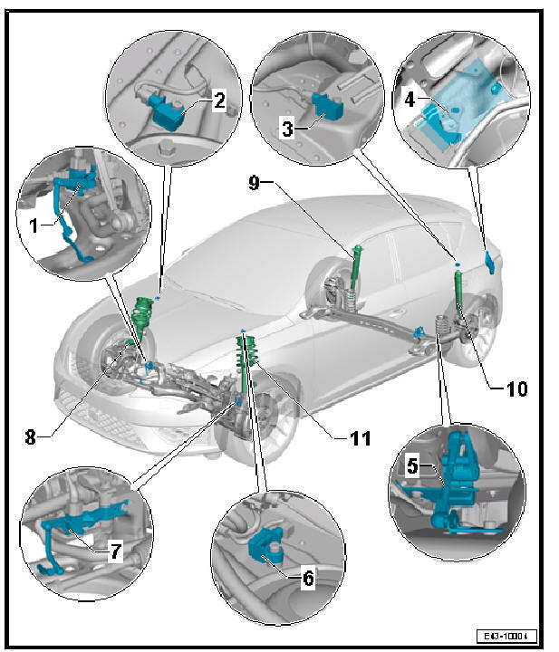
- - Front right vehicle level
sender - G289-
- Removing and installing
- - Front right body acceleration
sender - G342-
- Removing and installing
- - Body acceleration sender,
rear - G343-
- Location: on left suspension strut dome behind left side panel trim in luggage compartment.
- Removing and installing
- - Electronically controlled
damping control unit - J250-
- Removing and installing
- Location: electronically controlled damping control unit - J250- is installed behind left side panel trim in luggage compartment.
- Function Replace control unit must be performed with - Vehicle diagnostic tester if electronically controlled damping control unit - J250- is renewed.
- If the reference position has been re-adapted, the front camera for driver assist systems must be recalibrated on vehicles with lane departure warning function
- - Vehicle level sender, left side of the rear part - G76-
- Removing and installing
- - Front left body acceleration sender - G341-
- Removing and installing
- - Front left vehicle level sender - G78-
- Removing and installing
- - Shock absorber with front right shock absorber damper adjustment valve
- N337-
- Removing and installing suspension strut
- Servicing suspension strut
- - Shock absorber with rear right shock absorber damper adjustment valve
- N339- .
- Removing and installing shock absorber
- Servicing shock absorber
- - Shock absorber with rear left shock absorber damper adjustment valve -
N338- .
- Removing and installing shock absorber
- Servicing shock absorber
- - Shock absorber with front left shock absorber damper adjustment valve
- N336-
- Removing and installing suspension strut
- Servicing suspension strut
Assembly overview - electronically controlled damping system, multi-link suspension, saloon
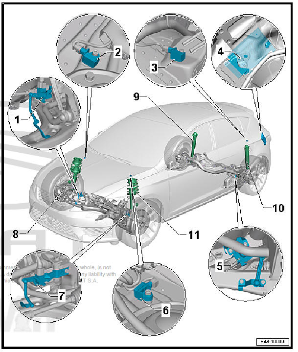
- - Front right vehicle level
sender - G289-
- Removing and installing
- - Front right body acceleration
sender - G342-
- Removing and installing
- - Body acceleration sender,
rear - G343-
- Location: on left suspension strut dome behind left side panel trim in luggage compartment.
- Removing and installing
- - Electronically controlled
damping control unit - J250-
- Removing and installing
- Location: electronically controlled damping control unit - J250- is installed behind left side panel trim in luggage compartment.
- Function Replace control unit must be performed with - Vehicle diagnostic tester if electronically controlled damping control unit - J250- is renewed.
- If the reference position has been re-adapted, the front camera for driver assist systems must be recalibrated on vehicles with lane departure warning function
- - Vehicle level sender, left side of the rear part - G76-
- Removing and installing, front-wheel drive
- - Front left body acceleration sender - G341-
- Removing and installing
- - Front left vehicle level sender - G78-
- Removing and installing
- - Shock absorber with front right shock absorber damper adjustment valve
- N337-
- Removing and installing suspension strut
- Servicing suspension strut
- - Shock absorber with rear right shock absorber damper adjustment valve
- N339- .
- Removing and installing shock absorber
- Servicing shock absorber
- - Shock absorber with rear left shock absorber damper adjustment valve -
N338- .
- Removing and installing shock absorber
- Servicing shock absorber
- - Shock absorber with front left shock absorber damper adjustment valve
- N336-
- Removing and installing suspension strut
- Servicing suspension strut
Assembly overview - electronically controlled damping system, multi-link suspension, variant

- - Front right vehicle level
sender - G289-
- Removing and installing
- - Front right body acceleration
sender - G342-
- Removing and installing
- - Body acceleration sender,
rear - G343-
- Location: on left suspension strut dome behind left side panel trim in luggage compartment.
- Removing and installing
- - Electronically controlled
damping control unit - J250-
- Removing and installing
- Location: electronically controlled damping control unit - J250- is installed behind left side panel trim in luggage compartment.
- Function Replace control unit must be performed with - Vehicle diagnostic tester if electronically controlled damping control unit - J250- is renewed.
- If the reference position has been re-adapted, the front camera for driver assist systems must be recalibrated on vehicles with lane departure warning function
- - Vehicle level sender, left side of the rear part - G76-
- Removing and installing front-wheel drive
- Removing and installing four-wheel drive
- - Front left body acceleration sender - G341-
- Removing and installing
- - Front left vehicle level sender - G78-
- Removing and installing
- - Shock absorber with front right shock absorber damper adjustment valve
- N337-
- Removing and installing suspension strut
- Repairing suspension strut
- - Shock absorber with rear right shock absorber damper adjustment valve
- N339- .
- Removing and installing shock absorber
- Servicing shock absorber
- - Shock absorber with rear left shock absorber damper adjustment valve -
N338- .
- Removing and installing shock absorber
- Servicing shock absorber
- - Shock absorber with front left shock absorber damper adjustment valve
- N336-
- Removing and installing suspension strut
- Repairing suspension strut

 Removing and installing electronically
controlled damping control unit - J250-
Removing and installing electronically
controlled damping control unit - J250-
Removing and installing electronically
controlled damping control unit - J250- ,
saloon
Special tools and workshop equipment required
Vehicle diagnosis tester
Removing
Location: electronica ...
See also:
Separation element: removing and installing
Special tools and workshop equipment required
Release lever - 3409-
Removing
Note
The sequences below describe the processes for removal and
installation for the left side of the vehicle. ...
