Seat Leon >> Removing and installing drive shaft
Removing and installing drive shaft, left drive shaft, constant velocity joints VL100 and VL107
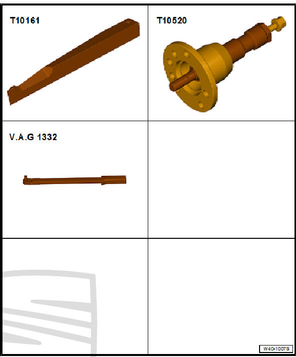
Special tools and workshop equipment required
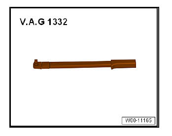
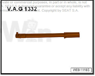
- Torque wrenches - V.A.G 1332-
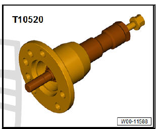
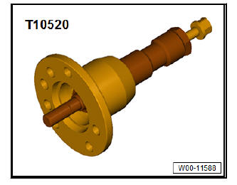
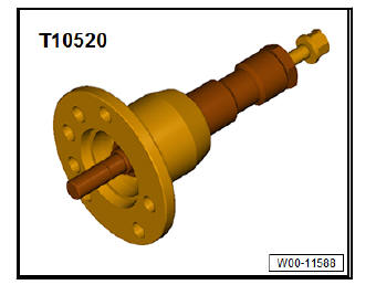
- Puller - T10520-
| Caution When carrying out dismounting and assembly work in the vehicle, the drive shafts should not be left hanging, nor should they be bent too far in order to fit them in the joint. |
Removing
- Remove bolt for drive shaft
| Caution Wheel bearings must not be subjected to load after loosening bolt securing drive shaft at wheel hub. If they have to support the weight of the vehicle they will be damages and their service life will be reduced. It is not permissible to turn drive shaft bolt more than 90º anticlockwise if vehicle is standing on its wheels. Do not attempt to move the vehicle without the drive shafts fitted; this would result in wheel bearing damage. If it is necessary for a vehicle to be moved, please comply with the following instructions:
|
- Remove front wheel on affected side.
- If fitted, remove noise insulation.
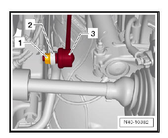
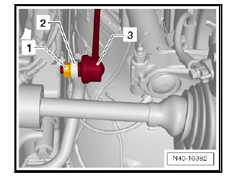
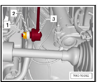
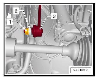
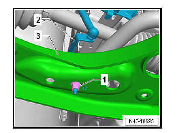
- Unscrew the hexagonal nut -1- from the link bar -3-.
- Pull coupling rod -3- out of anti-roll bar -2-.
Vehicles with vehicle level senders
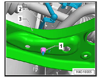
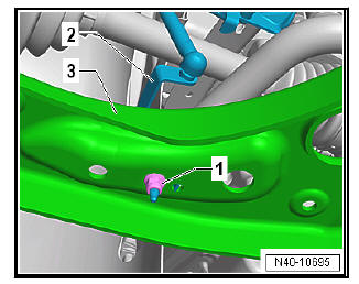
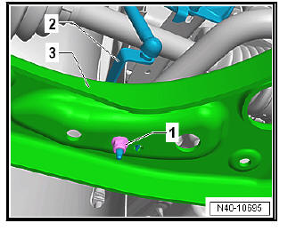
- Remove nut -1-.
- Pull bracket -2- for front left vehicle level sender - G78- and/or for front right vehicle level sender - G289- out of suspension link -3-, as applicable
Continuation for all models:
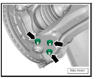
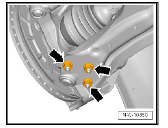
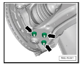
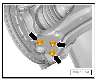
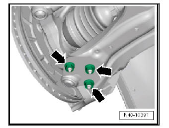
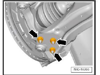
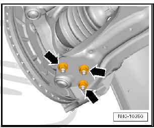
- Remove nuts -arrows- on swivel joint.
- Detach wishbone from swivel joint.
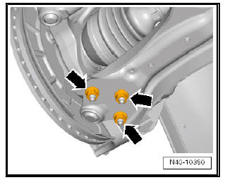
- Unbolt drive shaft from gearbox flange shaft -arrows-.
- Turn wheel bearing housing to left.
- Pull drive shaft out of wheel hub.
If the drive shaft cannot be pulled out of the wheel bearing by hand, use press tool - T10520- .
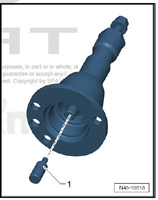
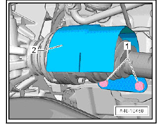
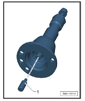
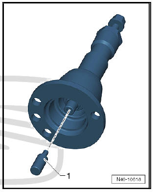
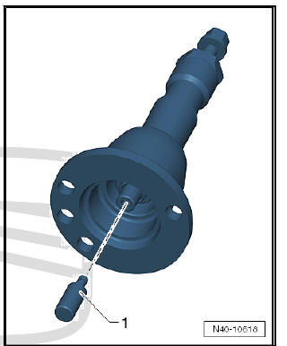
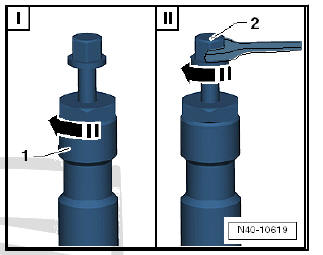
Before using press tool - T10520- ensure that thrust piece -1- is inserted.
Using press tool - T10520- :
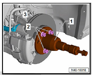
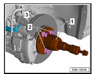
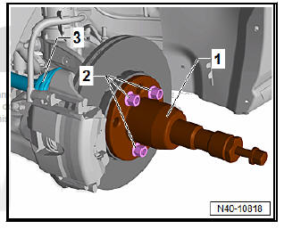
- To be able to press out the drive shaft -3-, secure press tool - T10520- -1- to the wheel hub -2- using 3 wheel bolts.
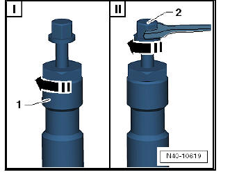
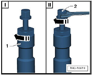
- It is essential to follow specified sequence.
I - Tighten knurled nut -1- hand-tight.
II - Turn only bolt -2- using a spanner in order to press out drive
shaft with press tool - T10520- .
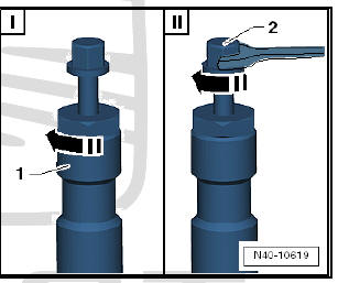
Note At the end of the procedure or for pressing out drive shaft further the spindle must be moved to its original position in order to deploy the hydraulic force!
- Remove drive shaft.
Installing
Carry out installation in the reverse sequence, noting the following:
- Tighten nuts -arrows-.
Note Tighten nuts -arrows- in unladen state.
Note
- Lever on vehicle level sender must face towards outside of vehicle.
- Thread of vehicle level sender must be screwed into outer hole in suspension link. Retaining lug for vehicle level sender must engage in inner hole in order to guarantee correct installation position.
- On vehicles with vehicle level sender, carry out basic settings for wheel damper electronics - Vehicle diagnostic tester.
Specified torques
- Bolts for noise insulation.
- On vehicles with vehicle level sender, carry out basic adjustment of headlights.
Removing and installing drive shaft, right drive shaft, constant velocity joints VL100 and VL107
Special tools and workshop equipment required
- Torque wrenches - V.A.G 1332
- Puller - T10520-
| Caution When carrying out dismounting and assembly work in the vehicle, the drive shafts should not be left hanging, nor should they be bent too far in order to fit them in the joint. |
Removing
- Remove bolt for drive shaft.
| Caution Wheel bearings must not be subjected to load after loosening bolt securing drive shaft at wheel hub. If they have to support the weight of the vehicle they will be damages and their service life will be reduced. It is not permissible to turn drive shaft bolt more than 90º anticlockwise if vehicle is standing on its wheels. Do not attempt to move the vehicle without the drive shafts fitted; this would result in wheel bearing damage. If it is necessary for a vehicle to be moved, please comply with the following instructions:
|
- Remove front wheel on affected side.
- Remove noise insulation.
- Unscrew nut -1- securing coupling rod -3-.
- Pull coupling rod -3- out of anti-roll bar -2-.
Vehicles with vehicle level senders
- Remove nut -1-.
- Pull bracket -2- for front left vehicle level sender - G78- and/or for front right vehicle level sender - G289- out of suspension link -3-, as applicable
Continuation for all models:
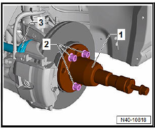
- If fitted, remove bolts -1- and detach heat shield -2- .
- Unbolt drive shaft from gearbox flange.
- Remove nuts -arrows- on swivel joint.
- Detach wishbone from swivel joint.
- Swivel out suspension strut and at the same time guide drive shaft out of wheel bearing unit.
If the drive shaft cannot be pulled out of the wheel bearing by hand, use press tool - T10520- .
Before using press tool - T10520- ensure that thrust piece -1- is inserted.
Using press tool - T10520- :
- To be able to press out the drive shaft -3-, secure press tool - T10520- -1- to the wheel hub -2- using 3 wheel bolts.
- It is essential to follow specified sequence.
I - Tighten knurled nut -1- hand-tight.
II - Turn only bolt -2- using a spanner in order to press out drive
shaft with press tool - T10520- .
Note At the end of the procedure or for pressing out drive shaft further the spindle must be moved to its original position in order to deploy the hydraulic force!
- Remove drive shaft.
Installing
Carry out installation in the reverse sequence, noting the following:
- Tighten nuts -arrows-.
Note Tighten nuts -arrows- in unladen state.
Note
- Lever on vehicle level sender must face towards outside of vehicle.
- Thread of vehicle level sender must be screwed into outer hole in suspension link. Retaining lug for vehicle level sender must engage in inner hole in order to guarantee correct installation position.
- On vehicles with vehicle level sender, carry out basic settings for wheel damper electronics - Vehicle diagnostic tester.
Specified torques
- Bolts for noise insulation.
- On vehicles with vehicle level sender, carry out basic adjustment of headlights.
Removing and installing drive shaft, triple roller joint AAR3300i inserted
Special tools and workshop equipment required
- Wedge (aluminium) - T10161-
- Puller - T10520-
- Torque wrenches - V.A.G 1332-
| Caution When carrying out dismounting and assembly work in the vehicle, the drive shafts should not be left hanging, nor should they be bent too far in order to fit them in the joint. |
Removing
- Remove bolt for drive shaft
| Caution Wheel bearings must not be subjected to load after loosening bolt securing drive shaft at wheel hub. If they have to support the weight of the vehicle they will be damages and their service life will be reduced. It is not permissible to turn drive shaft bolt more than 90º anticlockwise if vehicle is standing on its wheels. Do not attempt to move the vehicle without the drive shafts fitted; this would result in wheel bearing damage. If it is necessary for a vehicle to be moved, please comply with the following instructions:
|
- Remove front wheel on affected side.
- If fitted, remove noise insulation.
- Unscrew nut -1- securing coupling rod -3-.
- Pull coupling rod -3- out of anti-roll bar -2-.
Vehicles with vehicle level senders
- Remove nut -1-.
- Pull bracket -2- for front left vehicle level sender - G78- and/or for front right vehicle level sender - G289- out of suspension link -3-, as applicable
Continuation for all models:
- Unscrew nuts -arrows-.
- Pull wheel bearing housing with swivel joint out of suspension link.
- Remove the drive shaft from the wheel hub and fasten to the bodywork.
If the drive shaft cannot be pulled out of the wheel bearing by hand, use press tool - T10520- .
Before using press tool - T10520- ensure that thrust piece -1- is inserted.
Using press tool - T10520- :
- To be able to press out the drive shaft -3-, secure press tool - T10520- -1- to the wheel hub -2- using 3 wheel bolts.
- It is essential to follow specified sequence.
I - Tighten knurled nut -1- hand-tight.
II - Turn only bolt -2- using a spanner in order to press out drive
shaft with press tool - T10520- .
Note At the end of the procedure or for pressing out drive shaft further the spindle must be moved to its original position in order to deploy the hydraulic force!
-
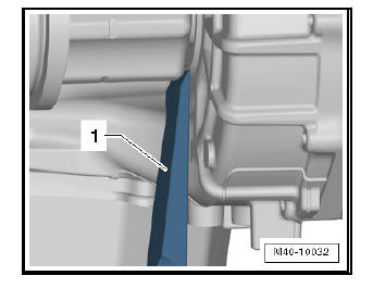
Insert wedge - T10161- -1- between gearbox housing and triple roller joint.
-
Press inner joint out of gearbox by striking wedge - T10161- with a rubber hammer.
-
Remove drive shaft.
Installing
Carry out installation in the reverse sequence, noting the following:
- Fit new retaining ring into groove of joint pin.
- Mesh outer and inner splines of joint body and gearbox.
- Hold the drive shaft by hand and insert it as far as possible into the joint casing.
- Push joint body into gearbox with a "forceful jolt".
The joint travel can be used for the "sudden push". Do not, however, pull the drive shaft too far out of the joint body.
| Caution Never use a hammer or other driving tools. |
- Check that the drive shaft is securely seated in the gearbox by pulling the joint body against the resistance of retaining ring.
| Caution For this check, pull only on joint body and not on drive shaft. |
- Guide outer joint into wheel hub splines as far as possible.
- Remove lower noise insulation.
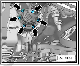
- Bolt the ball joint to the swinging arm -arrows-.
Note Ensure that bellows are not damaged or twisted.
Note
- Lever on vehicle level sender must face towards outside of vehicle.
- Thread of vehicle level sender must be screwed into outer hole in suspension link. Retaining lug for vehicle level sender must engage in inner hole in order to guarantee correct installation position.
- On vehicles with vehicle level sender, carry out basic settings for wheel damper electronics - Vehicle diagnostic tester.
Specified torques
- Bolts for noise insulation.
- On vehicles with vehicle level sender, carry out basic adjustment of headlights.
Removing and installing drive shafts, triple roller joint AAR3300i bolted
Special tools and workshop equipment required
- Torque wrenches - V.A.G 1332-
- Puller - T10520-
| Caution When carrying out dismounting and assembly work in the vehicle, the drive shafts should not be left hanging, nor should they be bent too far in order to fit them in the joint. |
Removing
- Remove bolt for drive shaft
| Caution Wheel bearings must not be subjected to load after loosening bolt securing drive shaft at wheel hub. If they have to support the weight of the vehicle they will be damages and their service life will be reduced. It is not permissible to turn drive shaft bolt more than 90º anticlockwise if vehicle is standing on its wheels. Do not attempt to move the vehicle without the drive shafts fitted; this would result in wheel bearing damage. If it is necessary for a vehicle to be moved, please comply with the following instructions:
|
- Remove front wheel on affected side.
- If present, remove lower noise insulation .
- Unscrew nut -1- securing coupling rod -3-.
- Pull coupling rod -3- out of anti-roll bar -2-.
Vehicles with vehicle level senders
- Remove nut -1-.
- Pull bracket -2- for front left vehicle level sender - G78- and/or for front right vehicle level sender - G289- out of suspension link -3-, as applicable
Continuation for all models:
- Unbolt drive shaft from gearbox flange shaft.
- Unscrew nuts -arrows-.
- Pull wheel bearing housing with swivel joint out of suspension link.
- Pull drive shaft out of wheel hub.
If the drive shaft cannot be pulled out of the wheel bearing by hand, use press tool - T10520- .
Before using press tool - T10520- ensure that thrust piece -1- is inserted.
Using press tool - T10520- :
- To be able to press out the drive shaft -3-, secure press tool - T10520- -1- to the wheel hub -2- using 3 wheel bolts.
- It is essential to follow specified sequence.
I - Tighten knurled nut -1- hand-tight.
II - Turn only bolt -2- using a spanner in order to press out drive
shaft with press tool - T10520- .
Note At the end of the procedure or for pressing out drive shaft further the spindle must be moved to its original position in order to deploy the hydraulic force!
Installing
Carry out installation in the reverse sequence, noting the following:
Note Remove any paint residues and/or corrosion on thread and splines of outer joint.
- Fit the drive shaft.
- Guide outer joint into wheel hub splines as far as possible.
- Bolt the ball joint to the swinging arm -arrows-.
Note Ensure that bellows are not damaged or twisted.
- Fit the interior drive shaft joint and tighten the bolts in diagonal pairs to a torque of 10 Nm.
- Tighten multi-point socket-head bolts diagonally to the specified torque.
Note
- Lever on vehicle level sender must face towards outside of vehicle.
- Thread of vehicle level sender must be screwed into outer hole in suspension link. Retaining lug for vehicle level sender must engage in inner hole in order to guarantee correct installation position.
- On vehicles with vehicle level sender, carry out basic settings for wheel damper electronics - Vehicle diagnostic tester.
- Remove lower noise insulation .
- Tighten drive shaft bolt at wheel hub.
Specified torques
- Bolts for noise insulation.
 Assembly overview - drive shaft
Assembly overview - drive shaft, constant velocity joint VL100
- Outer constant velocity joint
Always replace completely
Removing
Installing: drive onto
shaft as far as stop using
...
 Loosening and tightening drive shaft
bolt
Loosening and tightening drive shaft
bolt
Special tools and workshop equipment required
Socket, AF 24 - T10361 A
Digital Torque wrench - VAG 1756A-
CautionWheel bearings must not be subjected to load
after loosenin ...
See also:
Removing and installing radiator grille
Removing and installing radiator grille
Special tools and workshop equipment required
Release lever - 3409-
Removing
CautionWhen removing the upper grille from the bumper
trim pa ...
