Seat Leon >> Removing and installing steering box
Removing and installing steering box, left-hand drive vehicle
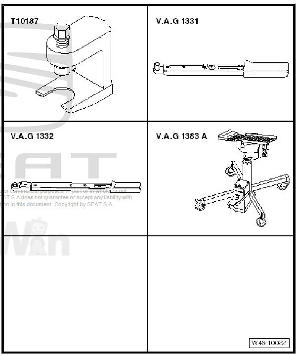
Special tools and workshop equipment required
- Ball joint puller - T10187-
- Torque wrenches - V.A.G 1331-
- Torque wrenches - V.A.G 1332-
- Engine elevator - V.A.G 1383 A-
Removing
- To prevent unintentional turning, secure steering wheel in straight-ahead position with adhesive tape -arrow-.
Note
- Only use adhesive tape that can be completely removed afterwards without leaving marks.
- Do not turn steering wheel while performing repair work, as otherwise airbag coil connector and return ring with slip ring - F138- could be damaged.
- Pull out the ignition key to lock the steering wheel.
Vehicles with keyless locking and starting system "Keyless Access"
- Switch off ignition and open driver's door so that the steering lock engages.
Continuation for all models:
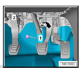
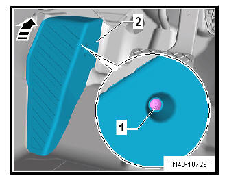
- Unscrew bolts -1- and fold footwell trim -2- in direction of arrow towards vehicle interior.
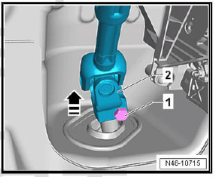
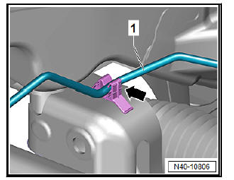
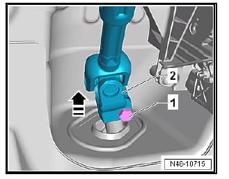
- Unscrew bolt -arrow- from universal joint -1- and pull off universal joint in -direction of arrow-.
| Caution The following work must not be performed while the universal joint is separated from the steering rack:
Not adhering to these instructions will result in irreparable damage. |
- Remove front wheels.
- Remove lower noise insulation.
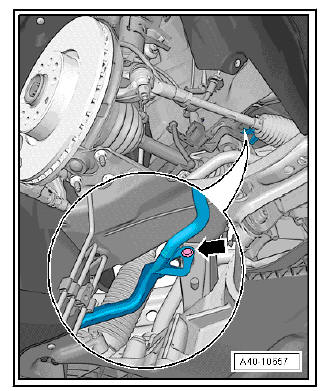
Vehicles with natural gas engines
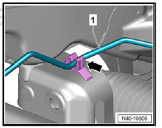
- Detach natural gas line -1- from clip -arrow-.
Continuation for all models:
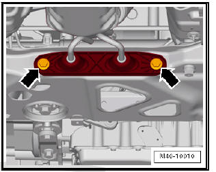
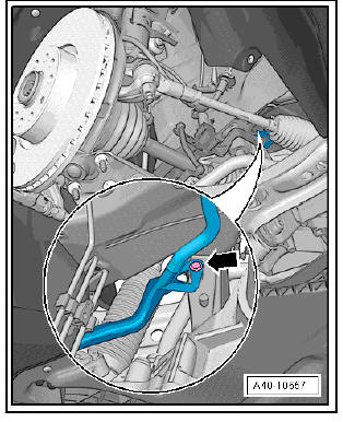
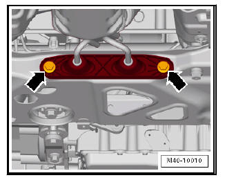
- Detach exhaust system bracket from subframe -arrows-.
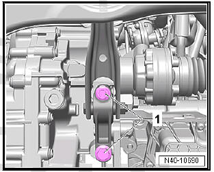
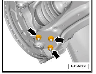
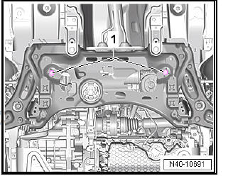
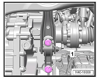
- Remove bolts -1- for pendulum support.
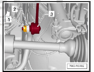
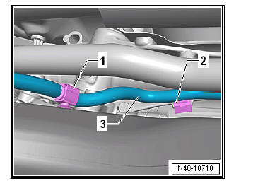
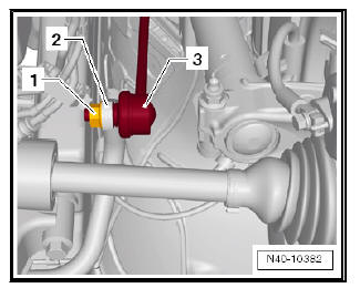
- Remove nut -1- from coupling rod -3- (left and right sides).
- Pull out coupling rod -3- from anti-roll bar -2- on left and right side.
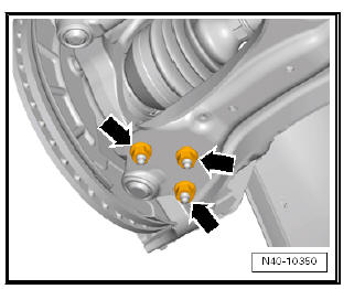
- Remove nuts -arrows- on both sides of vehicle.
- Pull swivel joint out of suspension link.
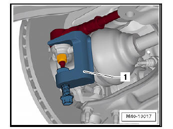
- Loosen nut on track rod ball joint but do not remove completely.
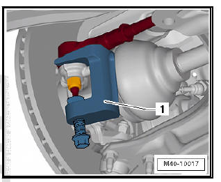
- Using ball joint puller - T10187- -1-, press track rod ball joint off wheel bearing housing, and unscrew nut.
| Caution Leave nut screwed several turns onto track rod ball joint shank to protect thread. |
Vehicles with vehicle level senders
- Disconnect connector -1- on front left vehicle level sender - G78- and/or front right vehicle level sender - G289- , as applicable.
Continuation for all models:
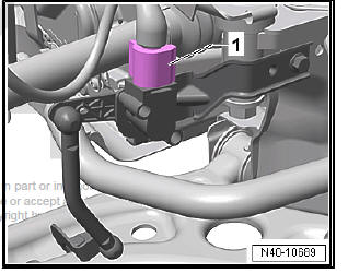
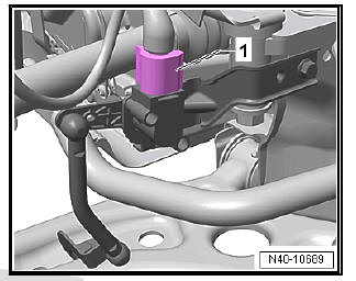
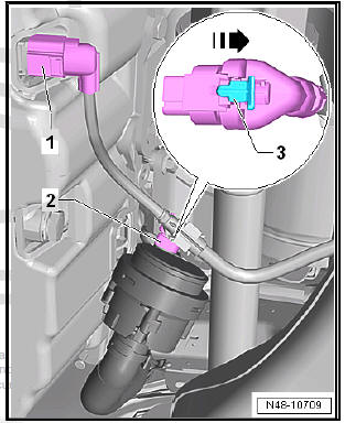
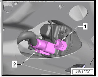
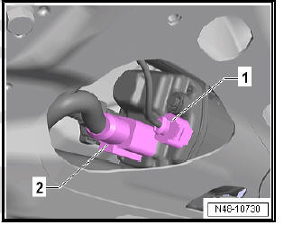
- Disconnect connector -1- of the oil level and oil temperature sender - G266- .
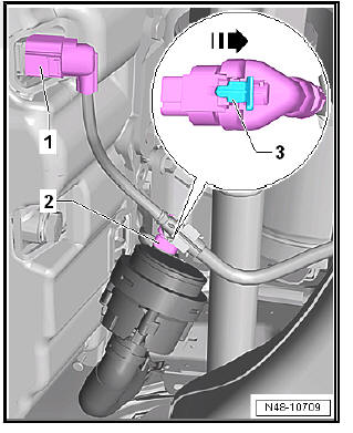
- If installed, disconnect connector -2- on continued coolant circulation pump - V51- . Open locking mechanism -3- in -direction of arrow-, and release connector.
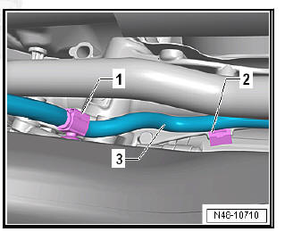
- Pull wiring harness -3- clips -1- and -2- off subframe and steering box.
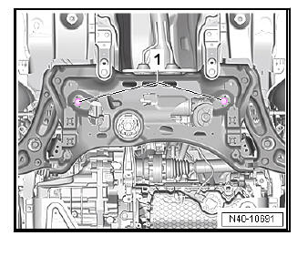
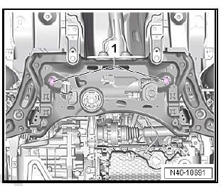
- Remove bolts -1- for steering box.
- Position engine and gearbox jack - V.A.G 1383 A- -1- under subframe.
- Fixing subframe and lowering approx. 10 cm.
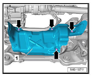
- Unscrew bolts -arrows- and remove heat shield -1- from steering box.
Note Different heat shields -1- are installed depending on the engine.
On some engines it is possible to access the connectors for the steering rack without removing the heat shield.
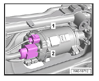
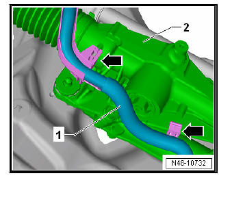
- Disconnect connectors -1- and -2- from steering rack.
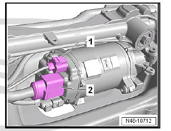
- Unclip wiring harness -1- from steering box -2- -arrows-.
- Pull out spreader clip -arrow-.
- Lower subframe with engine and gearbox jack - V.A.G 1383 A- .
- Prise steering box off subframe, for example with a large screwdriver, and remove to rear.
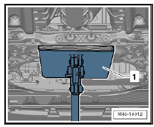
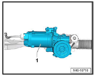
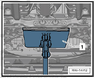
- Put steering box down as shown.
This prevents damage to control unit -1-.
Installing
Carry out installation in the reverse sequence, noting the following: The threaded bushings of the steering box should sit well in the openings of the strut.
- Plug in connectors -1- and -2- so that they engage audibly.
Note
- Coat seal on steering box with suitable lubricant, e.g. soft soap, before installing steering box.
- After fitting the steering box to the drive shaft ensure that the seal is not kinked against the assembly plate on the steering box. The opening to the footwell must seal correctly. Otherwise, noise or water may enter.
- Ensure sealing surfaces are clean.
- If a new steering box has been installed, the mounting holes of the heat shield have not yet been drilled. These are drilled when inserting the bolts of the shield.
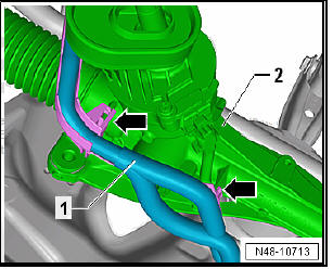
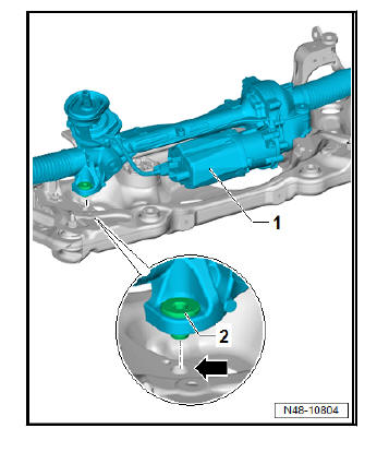
- Position steering rack -1- on subframe.
- Threaded sleeves -2- of steering rack must be inserted in holes in subframe -arrow-.
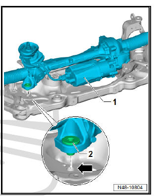
- Screw in bolts -1- for steering rack, and tighten them.
Note Ensure that bellows are not damaged or twisted.
- Remove lower noise insulation.
Note Ensure that bellows are not damaged or twisted.
- Bolt universal joint to steering box.
- Connect vehicle battery .
- Carry out basic setting for steering angle sender - G85- using - Vehicle diagnostic tester.
If new steering box has been installed, adapt electromechanical power-assisted steering using - Vehicle diagnostic tester.
Specified torques
- Bolts for pendulum support .
- Exhaust system to subframe .
- Bolts for noise insulation .
If even when using locating pins - T10486/1- a crooked steering wheel is determined during the road test, carry out a wheel alignment check. In this case the wheel alignment test results must be archived in the vehicle files.
Removing and installing steering box, right-hand drive vehicle
Special tools and workshop equipment required
- Ball joint puller - T10187-
- Torque wrenches - V.A.G 1331-
- Torque wrenches - V.A.G 1332-
- Engine/gearbox jack - V.A.G 1383 A-

Removing
- To prevent unintentional turning, secure steering wheel in straight-ahead position with adhesive tape -arrow-.
Note
- Only use adhesive tape that can be completely removed afterwards without leaving marks.
- Do not turn steering wheel while performing repair work, as otherwise airbag coil connector and return ring with slip ring - F138- could be damaged.
- Pull out the ignition key to lock the steering wheel.
Vehicles with keyless locking and starting system "Keyless Access"
- Switch off ignition and open driver's door so that the steering lock engages.
Continuation for all models:
- Unscrew bolt -1-.
- Push foot support -2- upwards in -direction of arrow- and remove.
- Fold floor covering to the rear.
- Unscrew bolt -arrow- from universal joint -1- and pull off universal joint in -direction of arrow-.
| Caution The following work must not be performed while the universal joint is separated from the steering rack:
Not adhering to these instructions will result in irreparable damage. |
- Remove front wheels.
- Remove lower noise insulation .
For vehicles with natural gas engines
- Detach natural gas line -1- from clip -arrow-.
Continuation for all models:
- Detach exhaust system bracket from subframe -arrows-.
- Remove bolts -1- for pendulum support.
- Remove nut -1- from coupling rod -3- (left and right sides).
- Pull out coupling rod -3- from anti-roll bar -2- on left and right side.
- Remove nuts -arrows- on both sides of vehicle.
- Pull swivel joint out of suspension link.
- Using ball joint puller - T10187- -1-, press track rod ball joint off wheel bearing housing, and unscrew nut.
| Caution Leave nut screwed several turns onto track rod ball joint shank to protect thread. |
Vehicles with vehicle level senders
- Disconnect connector -1- on front left vehicle level sender - G78- and/or front right vehicle level sender - G289- , as applicable.
Continuation for all models:
- Disconnect connector -1- for oil level and oil temperature sender - G266- .
- If fitted, disconnect connector -2- on continued coolant circulation pump - V51- . Open locking mechanism -3- in -direction of arrow-, and release connector.
- Pull wiring harness -3- clips -1- and -2- off subframe and steering box.
- Remove bolts -1- for steering box.

- Position engine and gearbox jack - V.A.G 1383 A- -1- under subframe.
- Fixing subframe and lowering approx. 10 cm.
- Disconnect connectors -1- and -2- from steering rack.
- Unclip wiring harness -1- from steering box -2- -arrows-.
- Pull out spreader clip -arrow-.
- Lower subframe with engine and gearbox jack - V.A.G 1383 A- .
- Prise steering box off subframe, for example with a large screwdriver, and remove to rear.
- Put steering box down as shown.
This prevents damage to control unit -1-.
Installing
Carry out installation in the reverse sequence, noting the following: The threaded bushings of the steering box should sit well in the openings of the strut.

- Plug in connectors -1- and -2- so that they engage audibly.
Note
- Coat seal on steering box with suitable lubricant, e.g. soft soap, before installing steering box.
- After fitting the steering box to the drive shaft ensure that the seal is not kinked against the assembly plate on the steering box. The opening to the footwell must seal correctly. Otherwise, noise or water may enter.
- Ensure sealing surfaces are clean.
- If a new steering box has been installed, the mounting holes of the heat shield have not yet been drilled. These are drilled when inserting the bolts of the shield.
- Position steering rack -1- on subframe.
- Threaded sleeves -2- of steering rack must be inserted in holes in subframe -arrow-.
- Screw in bolts -1- for steering rack, and tighten them.
Note Ensure that bellows are not damaged or twisted.
- Remove lower noise insulation .
Note Ensure that bellows are not damaged or twisted.
- Bolt universal joint to steering box.
- Connect vehicle battery.
- Carry out basic setting for steering angle sender - G85- using - Vehicle diagnostic tester.
If new steering box has been installed, adapt electromechanical power-assisted steering using - Vehicle diagnostic tester.
Specified torques
- Bolts for pendulum support .
- Exhaust system to subframe .
- Bolts for noise insulation .
If even when using locating pins - T10486/1- a crooked steering wheel is determined during the road test, carry out a wheel alignment check. In this case the wheel alignment test results must be archived in the vehicle files.
 Assembly overview - steering box
Assembly overview - steering box, left-hand drive
CautionThe following work must not be performed while
the universal
joint is separated from the steering rack:
Not adhering to these ...
 Dustguard: disassembly and assembly
Special tools and workshop
equipment required
Pliers for clamps - V.A.G
1275-
Torque wrenches - V.A.G
1332-
Tool insert 24 mm - V.A.G
1332/11-
Locking pliers for steering
box - VAS ...
See also:
Removing and installing door
Special tools and workshop equipment required
Torque wrench - V.A.G 1331-
Note
The sequences below describe the processes for removal and
installation for the left side of the vehicle. The ...
