Seat Leon >> Gear mechanism: repairing
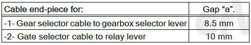
Identification of cable end-pieces
The holes on the cable securing elements have different diameters.
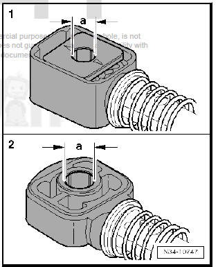
Installation position of gear selector lever and relay lever
- - Gear selection rod
- - Relay lever engages in guide rail of gearbox selector lever via shoe -arrow-.
Gate relay lever: grease following areas particularly thoroughly prior to installation
- Shaft -A- of gate relay lever -arrows-; amount of grease: 0.2 grams
- For grease allocation, refer to - Electronic parts catalogue (ETKA)
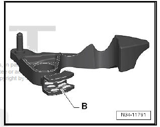
Gearbox selector lever: grease following areas particularly thoroughly prior to installation
- Guide rail -B- of gearbox selector lever into which gate relay lever engages
- Support pin for cable end-piece
- For grease allocation, refer to - Electronic parts catalogue (ETKA)
- The relay lever and gearbox selector lever may look different from the original part.
Install gearbox selector lever
- When fitting the gearbox selector lever, ensure that the gap -arrow A- is aligned with the master spline -arrow B-.
Relay lever: removing and installing
- Pull locking mechanism forwards in direction of -arrow 1- onto stop and then turn to left in direction of -arrow 2- to lock.
- Then push relay lever forwards (-direction of arrow 3-).
- Pull off clip -arrow 1- and remove relay lever together with cable end-piece.
Cable end-piece must be located behind catch -arrow 2-.
- It is only permissible to remove cable end-piece after relay lever has been removed .
- Press cable end-piece onto relay lever.
- Insert gate relay lever with cable end-piece as far as stop.
- Clip -arrow 1- secures the relay lever.
- Ensure proper engagement of clip.
- Cable end-piece must be located behind catch -arrow 2- (previous figure).
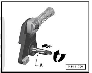
With gate relay lever removed: lever cable end-piece for gate selector cable off gate relay lever
- Relay lever has been removed
- Insert a flat-blade screwdriver -A- between bush -B- and relay lever.
Pressing on cable end-piece
- Relay lever has been removed
- Grease pin for cable end-piece
- For grease allocation, refer to - Electronic parts catalogue (ETKA) .
- Press on cable end-piece only at bush -arrow-.
- Cable end-piece must move freely on relay lever.
- It must be located behind catch -arrow 2-
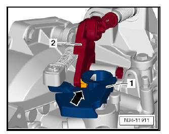
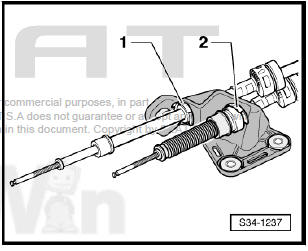
Installation position of securing clips -1- and -2-.
 Gear selection mechanism: removing
and fitting
Gear selection mechanism: removing
and fitting
Special tools and workshop equipment required
Torque wrenches - V.A.G 1331-
Removing
Disconnect battery .
Remove gear knob and gaiter .
Remove centre console mounting .
Remove noise ...
 Adjusting selector mechanism
Special tools and workshop equipment required
Locking pin - T10027A
Conditions for the adjustment
Drive and transmission elements of the gear drive mechanism
in perfect condition.
Sel ...
See also:
Removing and installing brake fluid reservoir
Removing and installing brake fluid reservoir,
left-hand drive vehicle
Special tools and workshop equipment required
Sealing tool - T10249-
Brake filling and bleeding equipment - VAS 523 ...
