Seat Leon >> Gearbox: disassembly and assembly
Removing and installing gearbox housing cover, clutch housing, selector shaft with selector mechanism cover, input shaft, output shaft, differential and selector mechanism.
Special tools and workshop equipment required
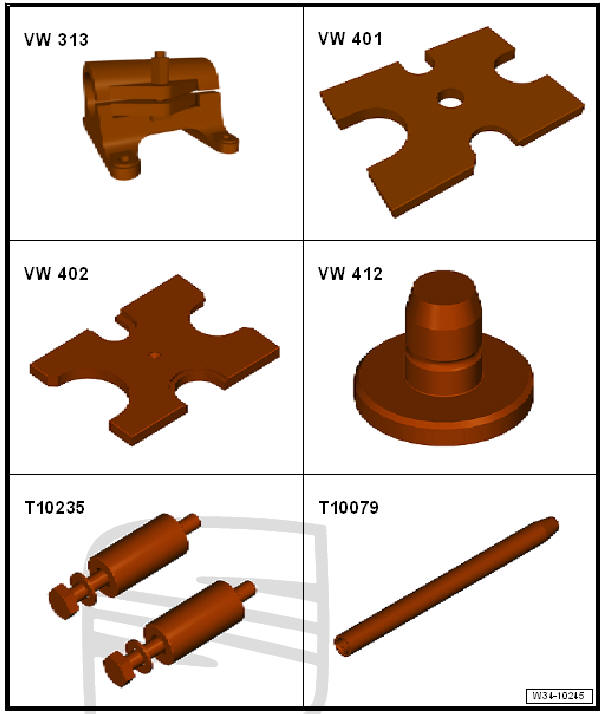
- Clamping frame - VW 313-
- Tightening plate - VW 401-
- Tightening plate - VW 402-
- Die - VW 412-
- Die - VW 407-
- Adapter - T10235-
- Guide pin - T10079-
- Engine and gearbox support - VW 540-
- Tray - V.A.G 1306-
- or drip tray for workshop hoist - VAS 6208-
- Torque wrenches - V.A.G 1331-
- Thrust block - T10083-
- Plate - T10083/1-
- Thrust pad - T10085-
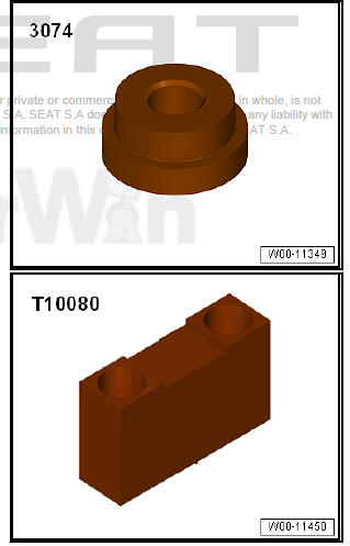
- Thrust pad - 3074-
- Press tool - T10080-
- Sealant
- Equivalent - Electronic spare parts catalogue (ETKA)
Gearbox disassembly
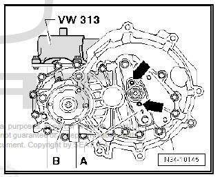
- Secure gearbox to engine and gearbox support - VW 540- -arrows-.
- Place drip tray underneath.
- Drain gear oil.
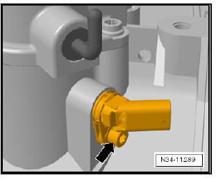
- Remove clutch release lever -A- with clutch release collar and guide sleeve -arrows-.
- Turn out fixing screw for flanged shaft right -B-.
- Screw 2 bolts into flange and counterhold flange shaft using a lever.
- Remove the flanged shaft with the compression spring, thrust washer and conic ring.
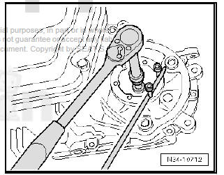
- Unscrew the gearbox casing cover -arrow- and remove with care.
- Pull out pivot pin -1- for 5th gear -2- and remove selector fork.
- Remove securing clip -3- for 5th gear synchro-hub.
- Remove locking collar with synchro-hub, synchromeshed gear for 5th gear with synchro-ring and needle bearing from output shaft.
- Remove securing clip -4- for gear wheel for 5th gear and remove gear wheel.

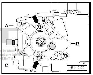
- Remove bearing mounting securing bolts -A- from input and output shafts.
- Unscrew hexagon collared nut -B- for securing reverse gear selector mechanism.
- Extract the flanged shaft securing bolt -C-. To do this, screw 2 bolts into flange and counterhold flange shaft with an assembly lever.
- Pull out flange shaft -C- with spring.
- Turn gearbox in support bracket so that clutch housing is upwards.
- Remove securing bolts from clutch housing side for securing clutch housing to gearbox housing.
- Remove clutch housing, if necessary carefully levering up all around along protruding housing flange and alternating between sides, being careful not to damage sealing surfaces.
- Do not cant the clutch housing. This prevents damage to roller bearings and their bearing seats on the input and output shafts.
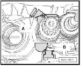
- Remove differential -A- from gearbox housing.
- Then remove oil collector -A- and oil guide -B- with magnet from gearbox housing.
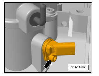
- Gearboxes for vehicles with start-stop system: remove gearbox neutral position sender - G701- -arrow-.
- Remove selector shaft with shaft cover -A-. To do so, the selector
shaft must be brought into the gearbox neutral position.
Then remove the bolts -arrows- and take the selector shaft out of the gearbox casing.
- Remove pivot pins -B- located on underside of gearbox.
- Unscrew reverse light switch -C-.
- Remove bolt -A- for securing reverse gear wheel shaft.
- Remove pivot pins -B- located on bottom of gearbox.
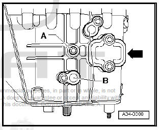
Note Do not remove the cover -arrows- to remove the gearbox.
- Press out input shaft, output shaft with bearing mounting, selector mechanism (selector forks) and reverse gear together.
Note
- Position gearbox housing so that dowel sleeves in the gearbox will not be damaged.
- When pressing out, get help from second mechanic to ensure components do not fall out.
- Release the input and secondary shafts from the allotment with the grooved ball bearings.
Assembling gearbox
Note
- Insert the allotment with grooved ball bearings for the input and secondary shafts.
- Pressing sleeve for 5th speed selector gear needle roller bearing onto input shaft.
- After assembly of the components, place drive shaft -2- and output shaft -1- with bearing mounting/grooved ball bearing in the thrust block - T10085- .
- Insert selector mechanism (selector forks) -4- in the shaft locking collars.
- Install reverse gear shaft -3- with reverse gear.
- Screw guide pin - T10079- onto stud (secures reverse gear) -arrow-.
- Insert components together in gearbox housing. To do this, guide guide pin - T10079- through hole for attachment of selector mechanism in gearbox housing.
- Unscrew the guide pin - T10079- .
Before adapting, the following must be checked.
- Selector forks engage correctly in locking collars.
- Dimension -a- of the input shaft splines.
Note
- The input shafts of the different gearboxes have different lengths as dimension -a- is different.
- A shim - T10083/1- (3 mm thick) may have to be fitted on the input shaft to ensure that the input shaft and the output shaft are always pressed in evenly.
- For this person, dimension -a- of the secondary shaft splines has to be measured.

Place shim - T10083/1- onto input shaft and carefully press in bearing mounting together with input shaft and output shaft to stop
Carefully press in bearing mounting together with input shaft and output shaft to stop.
- Install bolt -A- for securing reverse gear wheel shaft.
- Install pivot pin -B- in bottom of gearbox.
Note Sealing cover -arrow- is installed.
- Install pivot pin -B- in top of gearbox.
- Move selector plates and selector shaft to neutral.
- Apply sealant evenly to sealing surface of selector mechanism cover.
- Install selector shaft with selector cover -A-. Then tighten bolts -arrows-.
- Screw in reversing light switch - F4- -C-.
- Gearbox for vehicles with start-stop system: install gearbox neutral position sender - G701- -arrow- and tighten the bolt to the corresponding tightening torque.
- Using new bolts -A-, tighten bearing mounting for input and output shafts.

Note Tighten the bolts in stages to the specified torque in diagonal sequence, starting in the centre.
- Tighten hexagon flange nut -B- for selector mechanism (selector forks).
- Next, place the oil collector -A- in the recess -1- and in the drill hole -2- of the gearbox casing.
- Now insert oil guide -B- into gearbox housing.
- Place the magnet on the oil guide -B-.
- Install differential -A-.
- Apply sealant evenly to sealing surface.
- Secure clutch housing to gearbox housing.
- Rotate the gearbox on the assembly stand so that the gearbox casing is facing upwards.
- Install gear wheel for 5th gear -1-.
Installation position of gear wheel for 5th gear:
The high shoulder -arrow- faces gearbox housing cover.
- Install 5th speed selector gear with needle bearing.
- Fit the 5th gear synchromesh ring on the mobile pinion
- Install 5th gear synchro-hub complete with locking collar and stop ring.
- Insert 5th gear selector fork -2- and push in pivot pin -1- to stop in -direction of arrow-.
- Determining the correct securing ring size -arrow-.
- Determine thickest possible retaining rings which will still fit for input shaft -3- and output shaft -4- and install them.
Available retaining rings - Electronic parts catalogue (ETKA)

- Tighten gearbox housing cover.
- Fit the two flanged shafts with the pressure springs, the thrust washers and the conical rings.
- Install clutch release lever together with release bearing and guide sleeve.
Specified torques
- Gearbox housing to clutch housing
- Gearbox housing cover
- Flange shaft to gearbox (countersunk bolt)
 Schematic overview - gearbox
- 1st gear
- 2nd gear
- 3rd gear
- 4th gear
- 5th gear
- Gearbox casing cover
- Gearbox housing
- Reverse gear wheel
- Selector mechanism
(Gear change prongs)
- Clutch ...
 Assembly overview - selector unit
Note
Lubricate bearing positions and sliding surfaces.
For grease allocation, refer to - Electronic parts catalogue
(ETKA) .
- Shift collar
For the gear selection
shaft
Press ...
See also:
Convenience opening and closing*
Using the door lock
– Hold the key in the door lock of the driver door in either the
locking or the unlocking position until all windows are either
opened or closed.
– Release the key to inter ...
