Seat Leon >> Removing gearbox
SEAT Leon Service and Repair Manual / 5-speed manual gearbox 0AH / Controls, housing / Gearbox: removing and installing / Removing gearbox
Special tools and workshop equipment required
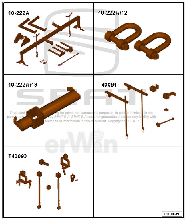
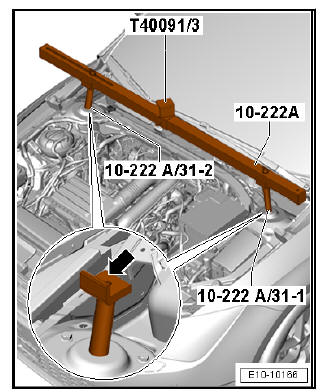
- Support. - 10 - 222 A-
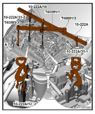
- Shackle - 10 - 222 A /12-
- Adapter for the engine bracket - 10 222A/18-
- Square pipe - T40091/1- and connector - T40091/3-
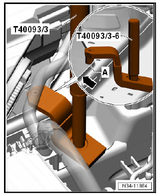
- Spindle from engine support supplement set - T40093 /3-
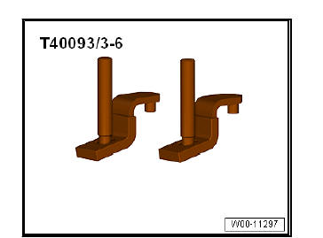
- Adapter - T40093/3 6-
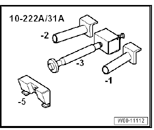
- Engine support bracket - 10 - 222 A /31A- , adapter - 10 - 222 A /31-1- , adapter - 10 - 222 A /31-2-
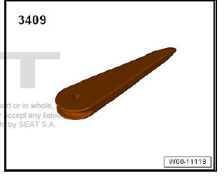
- Removal wedge - 3409-
Prepare tool
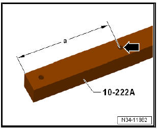
- If adapter -10 - 222 A- does not yet have hole (marked with
-arrow-), hole must now be drilled into adapter.
- Dimension -a- = 225 mm
- Drill Ø: 12.5 mm.
- Remove battery and battery tray .
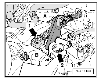
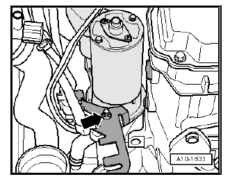
- Remove securing clip -1- for gear selector cable from gearbox selector lever -B-.
- Remove relay lever -A- together with cable lock.
- Remove gearbox selector lever -B- after removing the nut -arrow 2- .
- Unscrew bolts -arrows- and place cable support bracket to one side together with cables.
- Unscrew bolts -arrows- and place clutch slave cylinder to one side. Do not disconnect hoses/pipes.
| Caution Stop depressing clutch pedal. |
- Then remove upper securing bolt on starter.
- Remove upper engine/gearbox connecting bolts.
- If there are hose and cable connections in area of engine attachment eyes for the support bracket - 10 - 222 A- these must now be removed.
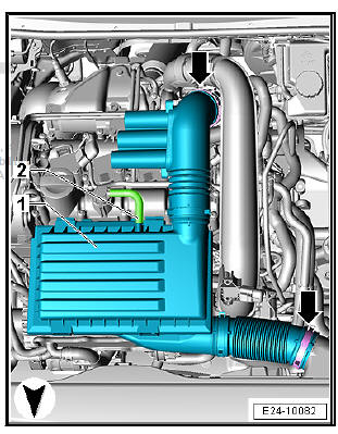
- Separate the air hose -2- from the air filter housing.
- Carefully remove the air filter housing -1- from the retaining bolts in an upward motion, sequentially.
- Loosen the brackets -arrow- for the air duct hose.
- Disconnect the air filter housing -1- with the air duct hoses.
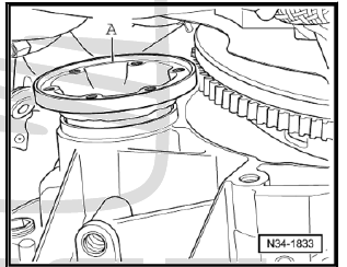
- Remove plenum chamber cover .
- Remove the caps on the screw connections of the suspension strut.
- Align support tool - 10-222 A- as follows:
- -10 - 222 A /31-1- and -10 - 222 A /31-2- place on the suspension strut mounts -arrow-.
- Slide the connector - T40091/3- over the gearbox support - 10-222 A- .
- Position the adapter -T40093/3-6- over the right crossbeam; if necessary, take the centre coolant tube out of its bracket.
- Bolt -A- must stay behind the edge -arrow-.
- Install the spindle of the auxiliary assembly kit of the support bracket for the engine - T40093 /3- .
- Connect the engine support bracket spindle supplementary kit - T40093 /3- to the support bracket - 10-222 A- via the square tube - T40091/1- and tension it.
- Hook spindles into engine support eyes using shackle - 10 - 222 A /12- .
- Take up weight of engine/gearbox assembly with spindle, but without raising it.
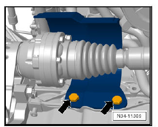
- Remove noise insulation.
- Remove the lower part of the front left wheel housing liner.
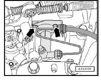
- Remove nut -arrow- and remove retainer for electrical lines.
- Remove starter .
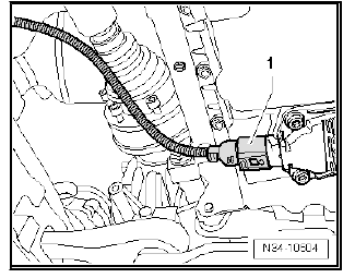
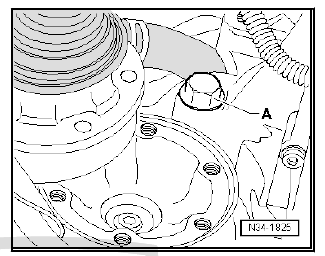
- Disconnect the connector -1- of the oil level and temperature sender - G266- .
- If present unscrew the indicator for the front vehicle level - G78- from the traverse link.
- Unplug electrical connectors:
- - Gearbox neutral position sender - G701-
- - Reversing light switch - F4-
| Caution Risk of damage to decoupling element.
|
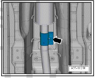
- Remove bolts -arrows- for exhaust pipe bracket from subframe.
- Disconnect exhaust system at clamp -arrow-.
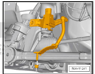
- Remove pendulum support.
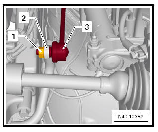
- Unscrew nut -1- from both sides of coupling rod -3-.
- Withdraw coupling rod -3- on both sides from anti-roll bar -2-.
- If required, remove drive shaft heat shield -Arrows-.
- Remove drive shafts from flange shafts and tie them up as high as possible, do not damage surface protection.
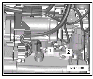
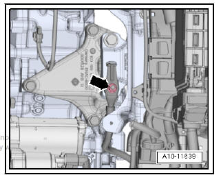
- Remove nut -arrow- and detach earth wire.
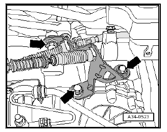
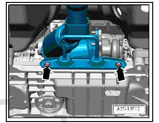
- Unscrew bolts -arrows 1- for gearbox mounting.
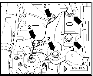
- Lower gearbox distance -a- by adjusting spindles of support
bracket - 10 - 222 A- .
- Dimension -a- = 60 mm
- Remove bolts -arrows 2- and detach gearbox support from gearbox.
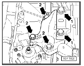
Unscrew bolts - 2, 3- of the connection between gearbox and engine.
- Unscrew bolts - 7, 8- of the connection between gearbox and engine.
- Bolts -1, 6, 9- securing gearbox to engine are unscrewed at a later stage.
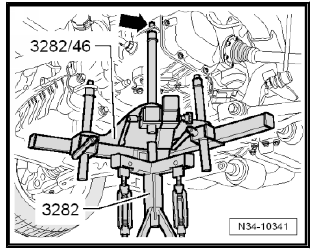
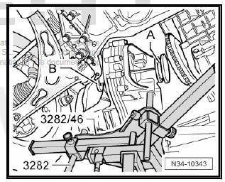
To remove gearbox "0AH" set up gearbox support - 3282- with adjustment plate - 3282/46- .
- Insert gearbox support - 3282- in engine and gearbox jack - V.A.G 1383 A- .
- Place adjustment plate - 3282/46- on gearbox support - 3282- .
- The adjustment plate can only be fitted in one position.
- Align arms of gearbox support according to holes in adjustment plate.
- Secure support elements as illustrated on adjustment plate.
- The arrow symbol on the adjustment plate points in the direction of travel. Align adjustment plate parallel with gearbox.
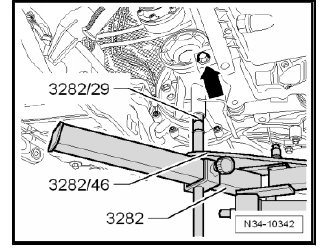
- Secure bolts - 3282/45- -arrow- to gearbox using a M 8 nut.
The bolts - 3282/45- should be flush below with the guide from the gearbox support - 3282- .
- Screw pin - 3282/29- into rear hole on gearbox for securing bolt of pendulum support.
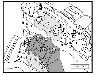
- Remove engine/gearbox connecting bolt -arrow-.
- Remove engine/gearbox connecting bolt - A-.
- Remove the remaining bolts connecting the engine to the gearbox.
- Press gearbox out of dowel sleeves and carefully swing towards front end.
- Carefully guide gearbox with right-hand flange shaft -A- past flywheel/intermediate plate.
- Turn gearbox in the area of the differential upwards and in the area of the 5th gear downwards.
- Lower gearbox, paying attention to the clearance of flange shaft -A- to flywheel and flange shaft -B- to subframe.
- If necessary, carefully push engine towards front (2nd mechanic required).
- On lowering it, modify the position of the gearbox using the spindles of the gearbox support unit - 3282- .
Note Pay attention to all pipes/hoses/wiring when lowering gearbox.
 Gearbox: removing and installing
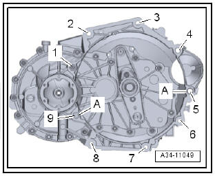
Specified torques for gearbox
Item -A- dowel sleeves for centring ...
 Installing gearbox
Note
Refer to procedure "Removing gearbox" for required special tools.
All threaded holes into which self-locking bolts are to be
screwed must be carefully cleaned of residual locking fluid usi ...
See also:
Removing and installing air duct for defroster
vent
Removal:
Turn off the ignition and all electricity consumers.
Vehicles without access and start authorisation system
Remove ignition key, if fitted.
Vehicles with access and start author ...
