Seat Leon >> Repairing subframe
Renewing bonded rubber bush (front)
Special tools and workshop equipment required
- Support tool - T10038-
- attachment tool - T10263-
- attachment tool - T10356-
- Engine/gearbox jack - V.A.G 1383 A-
- Hydraulic press - VAS 6178- and thrust piece - T10205/13-
- Foot pump - VAS 6179-
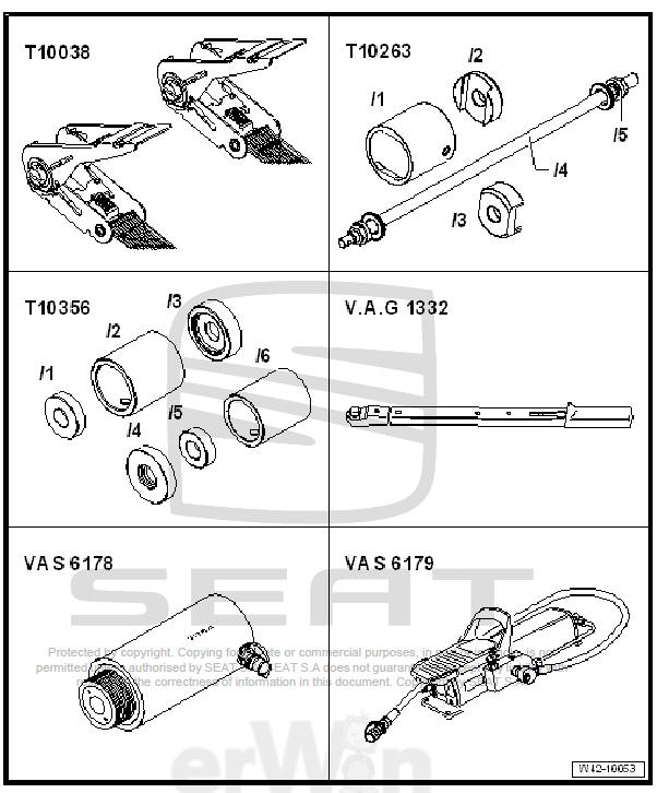
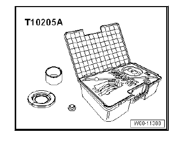
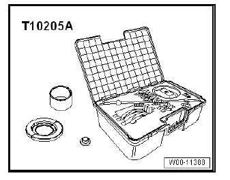
- attachment tool - T10205 A-
Note
- When a bonded rubber bush is defective, the bonded rubber bush on the opposite side must also be renewed, allocation - Electronic Parts Catalogue "ETKA" .
- Before replacing a defective bonded rubber bush, check the other bonded rubber bushes.
- If cracks or other damage are visible these bushes must also be renewed.
- The front or rear part of the subframe is lowered in order to renew the bonded rubber bushes. The subframe does not have to be removed.
- Mark the position of the bonded rubber bushes in relation to the subframe before removing them.
Pressing out bonded rubber bushes (front)
- Remove rear wheels.
- Remove the coil springs.
- Remove rear silencer for exhaust system.
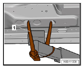
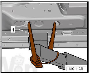
- Pull out retaining clip -1- on both sides of vehicle.
Note Do not open brake line.
- Use tensioning straps - T10038- to strap vehicle to support beams of lifting platform on both sides.
| WARNING If the vehicle is not strapped down, there is a great danger that the vehicle will slip off the lifting platform! |
- Locate subframe in position.
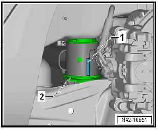
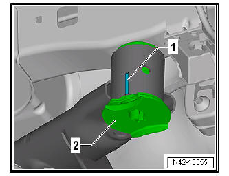
- Mark installation position of bonded rubber bush in relation to subframe -1- using a felt-tip pen or similar.
Note Make a mark -1- on subframe centred on cut-out in bonded rubber bush -2-.
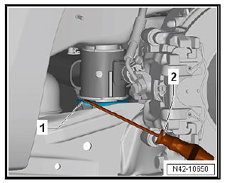
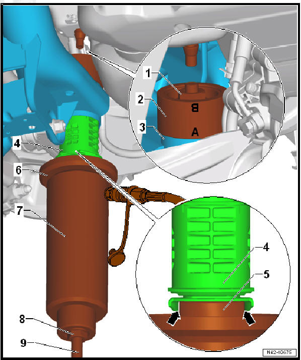
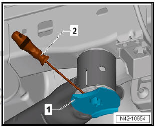
- Lever anti-twist device -1- off bonded rubber bush near retaining lug using, for example, a screwdriver -2-.
- Lower subframe approx. 100 mm with engine and gearbox jack - V.A.G 1383 A- .
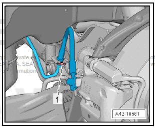
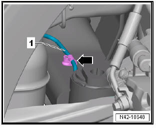
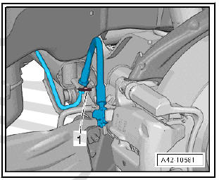
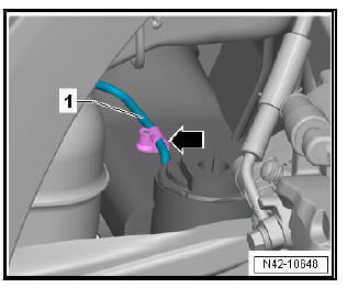
- Unclip brake line -1- from clip -arrow- on left side.
Note The clip will be destroyed and must be renewed.
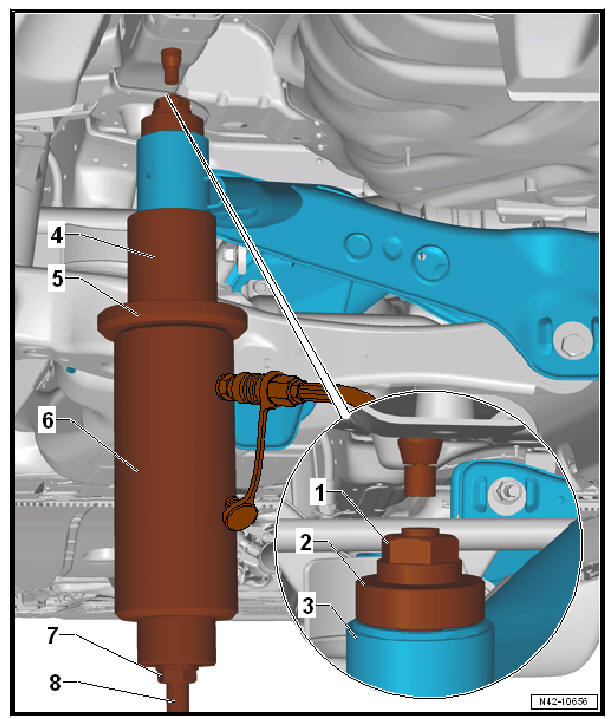
- Set up special tools as shown in illustration.
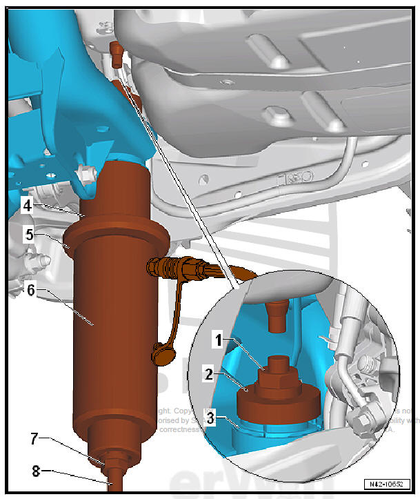
- - Hexagonal nut - T10263/5-
- - Thrust piece - T10356/1-
- - Subframe
- - Tube - T10356/2- side with cut-out facing towards subframe
- - Tightening plate - T10205/1-
- - Hydraulic press - VAS 6178- and thrust piece - T10205/13-
- - Hexagonal nut - T10263/5-
- - Threaded spindle - T10263/4-
- Take up play in special tools.
- Press out bonded rubber bush.
Note
- The shoulder of the outer ring of the bonded rubber bush is sheared off by the mounting when the bush is pulled out. This occurs with a loud bang.
- The bonded rubber bush must be removed from the tube - T10356/2- with light hammer blows once the bush has been pulled out.
Pressing in front bonded rubber bush
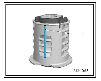
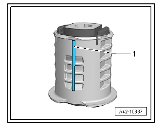
- As an assembly aid, draw a line -1- vertically on the shoulder of the bonded rubber bush.
- Coat outer edge of bonded rubber bush with assembly paste -G 294 421 A1-.
- Set up special tools with bonded rubber bush on subframe as shown.
- - Hexagonal nut - T10263/5-
- - Thrust piece - T10356/7- - the marking -A- faces towards subframe
- - Subframe
- - Align bonded rubber bush on mark, made for this purpose (the marks must align with one another)
- - Thrust piece - T10356/8- - the flattened sides must engage in cover of bonded rubber bush -arrows-.
- - Tightening plate - T10205/1-
- - Hydraulic press - VAS 6178- and thrust piece - T10205/13-
- - Hexagonal nut - T10263/5-
- - Threaded spindle - T10263/4-
- Check position of bonded rubber bush, align as required and take up play in special tools with bonded rubber bush.
Note
- Ensure that the hose from the hydraulic cylinder - VAS 6178- to the foot pump - VAS 6179- is routed between the trailing arm and the fuel tank while pressing in the bush.
- Ensure that the bonded rubber bush does not cant at the start of the pressing action. Otherwise, the outer ring could be damaged.
- Operate pump to press bonded rubber bush in until collar lies "flush" on subframe.
The remaining installation steps are carried out in reverse sequence - note the following points:
Specified torques
- Exhaust system
Renewing bonded rubber bush (rear)
Special tools and workshop equipment required
- Support tool - T10038-
- attachment tool - T10263-
- attachment tool - T10356-
- Engine/gearbox jack - V.A.G 1383 A-
- Hydraulic press - VAS 6178- and thrust piece - T10205/13-
- Foot pump - VAS 6179-
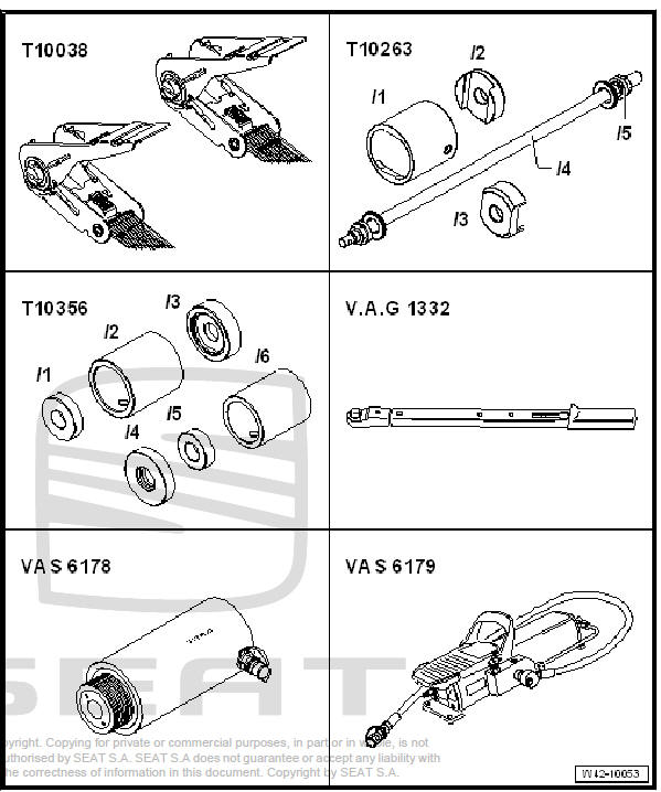
- attachment tool - T10205 A-
Note
- When a bonded rubber bush is defective, the bonded rubber bush on the opposite side must also be renewed, allocation - Electronic Parts Catalogue "ETKA" .
- Before replacing a defective bonded rubber bush, check the other bonded rubber bushes.
- If cracks or other damage are visible these bushes must also be renewed.
- The front or rear part of the subframe is lowered in order to renew the bonded rubber bushes. The subframe does not have to be removed.
- Mark the position of the bonded rubber bushes in relation to the subframe before removing them.
Pressing out bonded rubber bushes (rear)
- Remove rear wheels.
- Remove the coil springs.
- Remove rear silencer for exhaust system.
- Pull out retaining clip -1- on both sides of vehicle.
Note Do not open brake line.
- Use tensioning straps - T10038- to strap vehicle to support beams of lifting platform on both sides.
| WARNING If the vehicle is not strapped down, there is a great danger that the vehicle will slip off the lifting platform! |
- Locate subframe in position.
- Mark installation position of bonded rubber bush in relation to subframe -1- using a felt-tip pen or similar.
Note Make a mark -1- on subframe centred on cut-out in bonded rubber bush -2-.
- Lever anti-twist device -1- off bonded rubber bush near retaining lug using, for example, a screwdriver -2-.
- Lower subframe approx. 100 mm with engine and gearbox jack - V.A.G 1383 A- .
- Unclip brake line -1- from clip -arrow- on left side.
Note The clip will be destroyed and must be renewed.
- Set up special tools as shown in illustration.
- - Hexagonal nut - T10263/5-
- - Thrust piece - T10356/5-
- - Subframe
- - Tube - T10356/6- side with cut-out facing towards subframe
- - Tightening plate - T10205/1-
- - Hydraulic press - VAS 6178- and thrust piece - T10205/13-
- - Hexagonal nut - T10263/5-
- - Threaded spindle - T10263/4-
- Take up play in special tools.
- Press out bonded rubber bush.
Note
- The shoulder of the outer ring of the bonded rubber bush is sheared off by the mounting when the bush is pulled out. This occurs with a loud bang.
- The bonded rubber bush must be removed from the tube - T10356/6- with light hammer blows once the bush has been pulled out.
Pressing in rear bonded rubber bush
- As an assembly aid, draw a line -1- vertically on the shoulder of the bonded rubber bush.
- Coat outer edge of bonded rubber bush with assembly paste.
- Set up special tools with bonded rubber bush on subframe as shown.
- - Hexagonal nut - T10263/5-
- - Thrust piece - T10356/7- - the marking -B- faces towards subframe
- - Subframe
- - Align bonded rubber bush on mark, made for this purpose (the marks must align with one another)
- - Thrust piece - T10356/8- - the flattened sides must engage in cover of bonded rubber bush -arrows-.
- - Tightening plate - T10205/1-
- - Hydraulic press - VAS 6178- and thrust piece - T10205/13-
- - Hexagonal nut - T10263/5-
- - Threaded spindle - T10263/4-
- Check position of bonded rubber bush, align as required and take up play in special tools with bonded rubber bush.
Note Ensure that the bonded rubber bush does not cant at the start of the pressing action. Otherwise, the outer ring could be damaged.
- Operate pump to press bonded rubber bush in until collar lies "flush" on subframe.
The remaining installation steps are carried out in reverse sequence - note the following points:
Specified torques
- Exhaust system
 Secure the subframe
Fixing position of subframe, multi-link
suspension, front-wheel drive
Special tools and workshop equipment required
Locking device - T10096-
Engine/gearbox jack - VAS 6931-
Rear ...
 Anti-roll bar
...
See also:
Removing and installing filler neck compartment
lid
Special tools and workshop equipment required
Release lever - 3409-
Removing
Open tank flap
Insert - 3409- the lever into the recess and press the friction
finger -1- in -arrow direct ...
