Seat Leon >> Removing and installing lower suspension link
Removing and installing lower suspension link, vehicle with manual gearbox or dual clutch gearbox 0CW
Special tools and workshop equipment required
- Torque wrenches - V.A.G 1332-
Removing
- Remove front wheels.
- If fitted, remove noise insulation.
- Release rear area of wheel housing liner and fold it forwards.
Vehicles with vehicle level senders
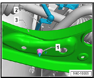
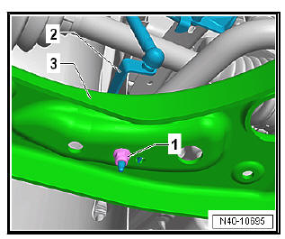
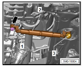
- Remove nut -1-.
- Pull bracket -2- for front left vehicle level sender - G78- and/or for front right vehicle level sender - G289- out of suspension link -3-, as applicable
Continuation for all models:
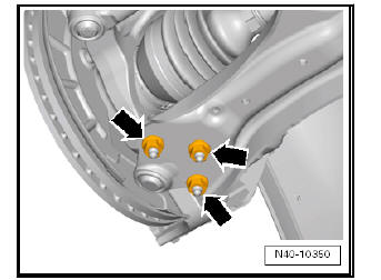
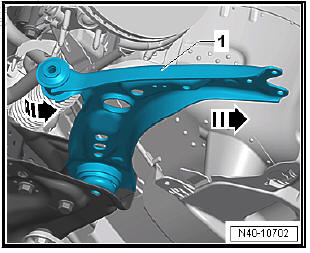
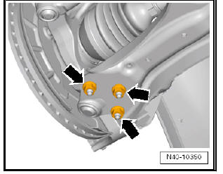
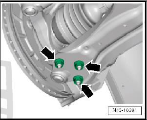
- Unscrew nuts -arrows-.
- Pull suspension link out of swivel joint and turn wheel bearing housing to outside to relieve suspension link.
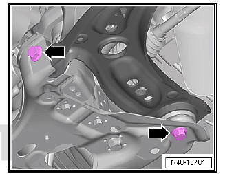
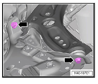
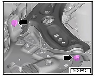
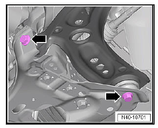
- Unscrew bolts -arrows-. Counterhold at rear bolt on nut at top while doing so.
Note The rear bolt is secured with a nut. Counterhold at nut when loosening.
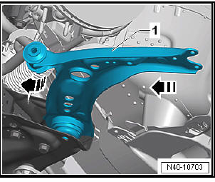
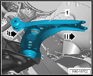
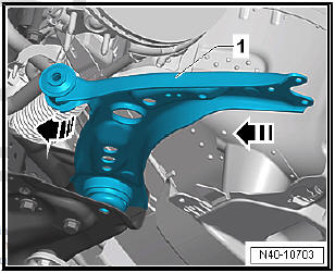
- Swivel suspension link -1- to rear and pull out of subframe in -direction of arrow-.
Installing
Carry out installation in the reverse sequence, noting the following:
- Insert rear suspension link -1- into subframe in -direction of arrow- and swivel forwards.
- Tighten bolts -arrow-.
Note
- Lever on vehicle level sender must face towards outside of vehicle.
- Thread of vehicle level sender must be screwed into outer hole in suspension link. Retaining lug for vehicle level sender must engage in inner hole in order to guarantee correct installation position.
- On vehicles with vehicle level sender, carry out basic settings for wheel damper electronics - Vehicle diagnostic tester
Specified torques
- Bolts for noise insulation
Removing and installing lower suspension link, vehicle with dual clutch gearbox 0D9
Special tools and workshop equipment required
- Torque wrenches - V.A.G 1332-
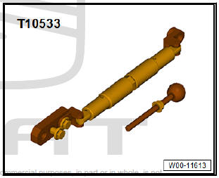
- Engine support - T10533-
Removing
- Remove front wheels.
- Remove noise insulation.
- Release rear area of wheel housing liner and fold it forwards.
Vehicles with vehicle level senders
- Remove nut -1-.
- Pull bracket -2- for front left vehicle level sender - G78- and/or for front right vehicle level sender - G289- out of suspension link -3-, as applicable
Continuation for all models:
- Unscrew nuts -arrows-.
- Pull suspension link out of swivel joint and turn wheel bearing housing to outside to relieve suspension link.
- Remove pendulum support .
- Loosen double clamp of exhaust system.
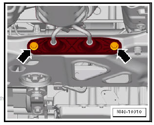
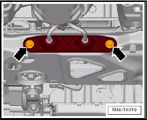
- Detach exhaust system bracket from subframe -arrows-.
- Press the engine support - T10533- fully together to as short a length as possible.
- Screw the engine support - T10533- -2- under large angle -arrow- onto the gearbox. To do this, use the short screws of the pendulum support screw connection -1-.
- Press the drive module forwards until the threaded rod - T10533/5- -3- can be inserted into the pendulum support bearing.
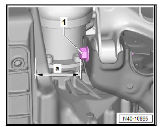
- Pull apart the engine support - T10533- , until the distance -a- between the screw of the axle guide -1- and the gearbox meets.
a = 85 mm
- Remove bolts -arrows-.
- Swivel suspension link -1- to rear and pull out of subframe in -direction of arrow-.
Installing
Installation is carried out in the reverse order. During this step, observe the following:
- Insert rear suspension link -1- into subframe in -direction of arrow- and swivel forwards.
- Tighten bolts -arrow-.
- Tighten nuts -arrows-.
Note Tighten nuts -arrows- in unladen state.
- Detach engine support - T10533- .
- Screw on double clamp for exhaust system.
- Install pendulum support.
- Install exhaust system bracket on the subframe -arrows-.
Continue installation in reverse order. During this step, observe the following:
Note
- Lever on vehicle level sender must face towards outside of vehicle.
- Thread of vehicle level sender must be screwed into outer hole in suspension link. Retaining lug for vehicle level sender must engage in inner hole in order to guarantee correct installation position.
- On vehicles with vehicle level sender, carry out basic settings for wheel damper electronics - Vehicle diagnostic tester.
Specified torques
- Bolts for pendulum support.
- Bolts for noise insulation.
- Exhaust pipes double clamp.
- Exhaust system to subframe.
Checking swivel joint
checking axial clearance
- Firmly pull suspension link down in -direction of arrow- and press up again.
Radial play: checking
- Press lower part of wheel forcefully inwards and outwards in -direction of arrow-.
Note
- During both checks there must be no discernible or visible "play".
- Observe swivel joint while performing tests.
- Take into account possible existing wheel bearing play or"play" in upper suspension strut mounting.
- Check the rubber bellows for possible damage, if necessary, replace the ball joint
 Lower suspension link, swivel joint
Assembly overview - lower suspension link, swivel joint
- Wheel bearing housing
Different versions possible.
Removing and installing
- Nut
Always renew after removing
60 Nm
...
 Removing and installing swivel joint
Special tools and workshop
equipment required
Ball joint puller - 3287 A-
Rotation angle spanner -
V.A.G 1756-
Insertable ring tool -
V.A.G 1332/10-
Special tools and workshop equipm ...
See also:
Dismantling and assembling drive shaft
Special tools and workshop
equipment required
Tightening plate - VW 401-
Tightening plate - VW 402-
Die - VW 408 A-
Die - VW 411-
Tube element - VW 416 B-
Thrust pad - VW 447 H
...
