Seat Leon >> Removing and installing suspension strut
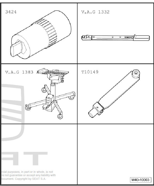
Special tools and workshop equipment required
- Torque wrenches - V.A.G 1332-
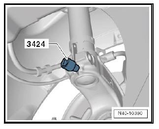
- Spreader - 3424-
- Engine elevator - V.A.G 1383 A-
- Mounting - T10149-
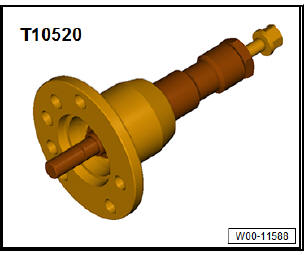
Special tools and workshop equipment required
- Puller - T10520-
Removing
- Loosen drive shaft bolt at wheel hub
| Caution Wheel bearings must not be subjected to load after loosening bolt securing drive shaft at wheel hub. If they have to support the weight of the vehicle they will be damages and their service life will be reduced. It is not permissible to turn drive shaft bolt more than 90º anticlockwise if vehicle is standing on its wheels. Do not attempt to move the vehicle without the drive shafts fitted; this would result in wheel bearing damage. If it is necessary for a vehicle to be moved, please comply with the following instructions:
|
- Remove front wheels.
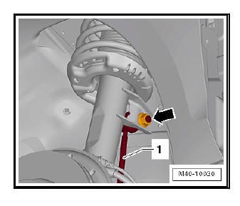
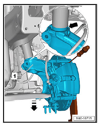
- Unscrew nut -arrow- and pull coupling rod -1- out from suspension strut.
- Detach wire for ABS speed sensor from suspension strut.
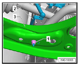
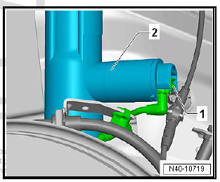
Vehicles with vehicle level senders
- Remove nut -1-.
- Pull bracket -2- for front left vehicle level sender - G78- and/or for front right vehicle level sender - G289- out of suspension link -3-, as applicable
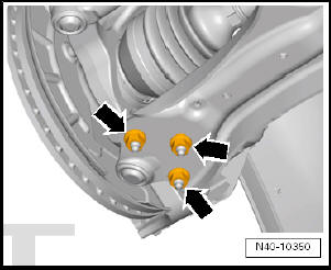
Continuation for all models:
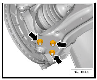
- Unscrew nuts -arrows-.
- Pull wheel bearing housing with swivel joint out of suspension link.
- Pull outer joint of drive shaft out of wheel hub.
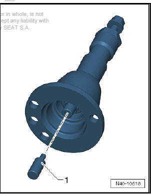
If the drive shaft cannot be pulled out of the wheel bearing by hand, use press tool - T10520- .
Before using press tool - T10520- ensure that thrust piece -1- is inserted.
Using press tool - T10520- :
- To be able to press out the drive shaft -3-, secure press tool - T10520- -1- to the wheel hub -2- using 3 wheel bolts.
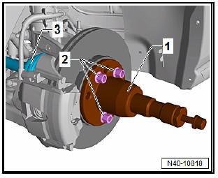
- It is essential to follow specified sequence.
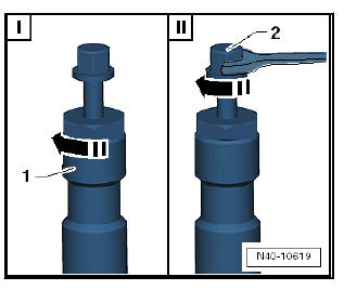
I - Tighten knurled nut -1- hand-tight.
II - Turn only bolt -2- using a spanner in order to press out drive
shaft with press tool - T10520- .
Note At the end of the procedure or for pressing out drive shaft further the spindle must be moved to its original position in order to deploy the hydraulic force!
- Secure drive shaft to body with wire.
| Caution Do not let the drive shaft hang down under its own weight, as otherwise excessive bending could damage the inner CV joint. |
Vehicles with adaptive chassis control DCC
- Disconnect connector -1- on shock absorber -2-.
Note If there is moisture in the area of the connector, blow compressed air on the contacts on the shock absorber and the connector.
Continuation for all models:
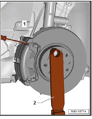
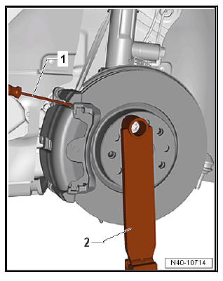
- Insert a screwdriver -1- into brake disc between brake caliper and brake carrier.
- Secure engine and gearbox jack - V.A.G 1383 A- with support - T10149- -2- to wheel hub using a wheel bolt.
WARNING
|
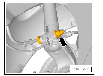
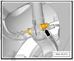
- Separate the threaded steering knuckle/suspension strut union -arrow-.
- Fit Separator device - 3424- in the steering knuckle groove
Note Make sure that the spreader - 3424- is only inserted into the wheel bearing housing. Insert sufficiently to ensure that the metal tab of the suspension strut is not damaged.
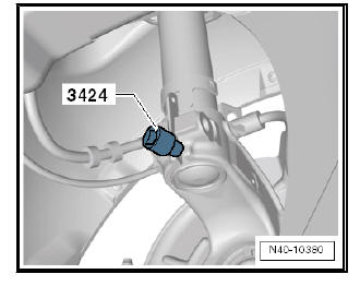
- Turn ratchet handle through 90º and detach from spreader - 3424- .
- Press brake disc towards suspension strut by hand.
Otherwise the shock absorber tube can cant in the bore of the wheel bearing housing.
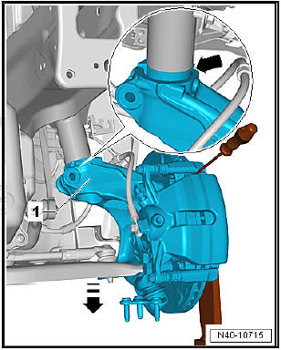
- Lower the wheel bearing housing -1- with the engine and gearbox jack - V.A.G 1383 A- in -direction of arrow-.
- Lower wheel bearing housing -1- until shock absorber is hanging free -arrow-.
- Bolt swivel joint to suspension link again and tighten wheel bearing housing to subframe.
- Pull engine and gearbox jack - V.A.G 1383 A- out from under support - T10149- .
WARNING
|
- Pull seal off entire length of plenum chamber cover.
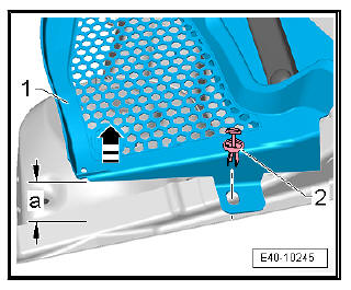
- Unclip the filler piece.
- Unhook the clips -2-.
- Lift plenum chamber cover -1- not more than 60 mm.
a - 60 mm
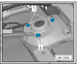
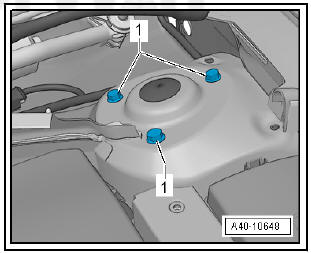
- Unscrew bolts -1- for upper shock absorber mounting and take out suspension strut.
Installing
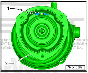
- Position suspension strut so that the arrow -1- is always on the inner side.
- One of the two arrows -1- on the spring plate -2- must point in direction of travel.
- Insert suspension strut and bolt bolts -1- to body.
- Position engine and gearbox jack - V.A.G 1383 A- under support - T10149- and secure wheel bearing housing.
- Untie wheel bearing housing from subframe.
- Unscrew nuts -arrows-.
- Pull wheel bearing housing with swivel joint out of suspension link.
- Lower the wheel bearing housing -1- with the engine and gearbox jack - V.A.G 1383 A- in -direction of arrow-.
- Push wheel bearing housing upwards with the engine and gearbox jack - V.A.G 1383 A- thus nearing the suspension strut.
- Bolt swivel joint to suspension link again and continue to press wheel bearing housing upwards until final position is reached on suspension strut.
- Detach support - 3424- .
- Insert new bolts, tip of bolt must point in direction of travel.
- Attach wheel bearing housing to suspension strut using new nut -arrow-.
Carry out installation in the reverse sequence, noting the following:
Note
- Lever on vehicle level sender must face towards outside of vehicle.
- Thread of vehicle level sender must be screwed into outer hole in suspension link. Retaining lug for vehicle level sender must engage in inner hole in order to guarantee correct installation position.
- On vehicles with vehicle level sender, carry out basic settings for wheel damper electronics.
 Suspension strut, upper suspension
link
Suspension strut, upper suspension
link
Assembly overview - suspension strut, upper suspension link
- Spring seat
Check fitting position
- Shock absorber
Different versions possible.
- Bolt
Always renew after ...
 Suspension strut - Repair
Special tools and workshop
equipment required
Torque wrenches - V.A.G
1332-
Spring tensor - V.A.G
1752/1-
Spring retainer - V.A.G
1752/4-
Shock absorber set -
T10001-
Commercially ...
See also:
Exploded view - wheel housing liner
Exploded view - wheel housing liner (front)
- Front wheel housing spoiler
PP/EPDM Material
- Front wheel housing liner
PP/EPDM Material
- Fixing block
7 off
- Bo ...
