Seat Leon >> Removing and installing heater and air conditioning unit
| WARNING Danger from refrigerant escaping under pressure! Freezing of skin and other body parts.
|
Special tools and workshop equipment required
- Hose clamps, up to 25 mm - 3094-
- Engine bung set - VAS 6122-
- Commercially available compressed-air gun
Removal:
- Turn off the ignition and all electricity consumers.
Vehicles without access and start authorisation system
- Remove ignition key, if fitted.
Vehicles with access and start authorisation system
- Store ignition key outside the vehicle to prevent the ignition from being switched on unintentionally.
Continued for all vehicles
- Disconnect battery.
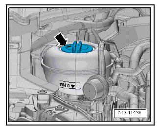
| WARNING Hot steam/hot coolant can escape - risk of scalding.
|
Open cap -arrow- on coolant expansion tank.
Vehicles with air conditioner
- Extract refrigerant.
- Detaching refrigerant pipe with internal heat exchanger from mount on the expansion valve.
Continue for all vehicles
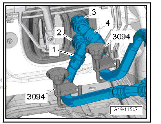
- Mark installation position of coolant hoses -1- and -4-.
Note The heat exchanger is designed for a certain coolant flow direction.
The coolant hoses must therefore be connected on the correct sides.
- Pinch off the coolant hoses with hose clamps -3094- .
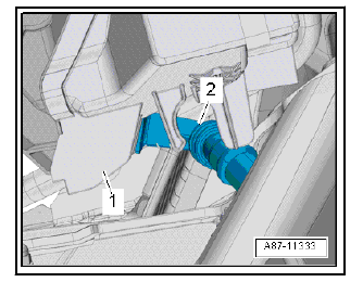
- Lift the fasteners -2, 3- and detach the coolant hoses from the heating system heat exchanger.
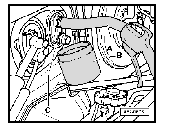
- Fit a short hose -A- to the upper connection.
- Insert the compressed air gun in the end of the hose.
- Hold a collector -B- under the lower connection -C- and use the compressed air gun to carefully blow the coolant out of the heat exchanger.
- Seal open lines and connections with clean plugs from the Engine sealing plug set - VAS 6122- .
Remove dash panel.
- Remove the rear footwell vent.
- If fitted: Remove the rear vent air duct .
- Unplug the connector -3- at the fresh air blower -1-.
- Place absorbent paper over the floor covering beneath the heater and air conditioning unit.
| WARNING Risk of airbag control unit malfunctioning due to corrosion in connector.
|
- Detach the condensation drain -2- from the heater and air conditioning unit -1-.
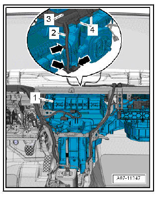
- Lay bare the duct -3-.
- Lay bare the wiring harness -2- at the mounts -4- -arrows-.
Note Do not remove the carrier for the onboard supply control unit - J519- and associated components: Onboard supply control unit - J519- , fuse boxC-SC-, control unit for parking aid - J446- , warning buzzer for front parking aid - H22- . The components mentioned may differ from one another depending on the vehicle fittings.
- Remove dash panel cross member.
- Unscrew the threaded locating pin on the left side of the cross member.
- Displace the dash panel cross member towards the back.
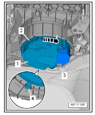
- Remove the heating and air conditioning unit -1- to right.
Installing
Install in reverse order of removal; note the following.
- Fill coolant.
- Vehicles with climate control: Fill refrigerant and refrigerant oil.
 Removing and installing supplementary
air heater element - Z35-
Removing and installing supplementary
air heater element - Z35-
Removal:
Turn off the ignition and all electricity consumers.
Vehicles without access and start authorisation system
Remove ignition key, if fitted.
Vehicles with access and start author ...
 Removing and installing holder for heater
and air conditioning unit
Removing and installing holder for heater
and air conditioning unit
Note
Leave the holders in the vehicle on removing the heater and air
conditioning unit.
Removal:
Turn off the ignition and all electricity consumers.
Vehicles without access and start author ...
See also:
Checking inner constant velocity joint
Removing
The joint is to be dismantled when following work is done:
Replacement of grease if very contaminated
Check of running surfaces for wear
Check of balls for wear
Swing ball hub ...
