Seat Leon >> Moving to and back from service position
Special tools and workshop equipment required
- Torque wrench - V.A.G 1331-
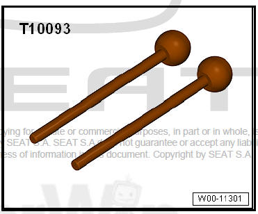
- Centre guide - T10093-
- Adapter - T10467-
| Caution The following is not necessary for positioning the lock carrier (with mechanical elements) in the service position:
|
Removing
| Caution It is not safe to use the bonnet support with the lock carrier in the service position. |
- Hold the bonnet tight with suitable workshop equipment.
- Remove the lower soundproofing of the engine .
- Remove bumper cover (front).
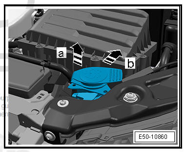
- Remove filler necks from washer fluid reservoir, to do this: slide necks in -direction of arrow a-.
- Clip out the support in the -direction of arrow b-.
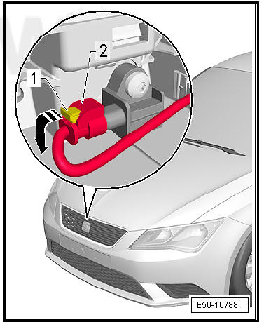
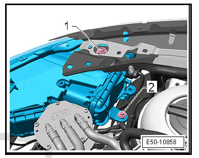
- Release clip -1- and remove air hose.
Note The configuration of the air supply ducts may vary depending on the engine version.
- Undo the screws -2- from both sides.
- Unclip the retaining clips of the air duct at lock carrier and detach.
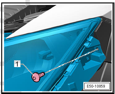
- Clip out and disconnect the plug connector of the bonnet contact switch - F266- .
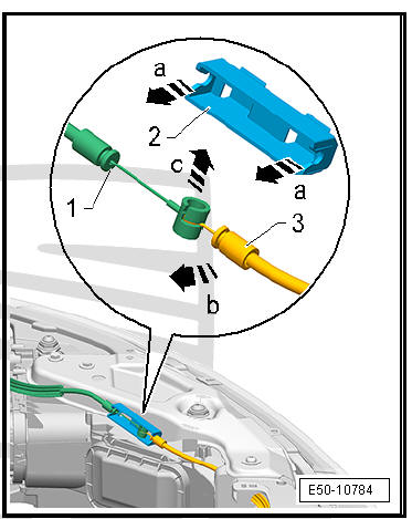
Separate the cable for opening the bonnet from the coupling sleeve. To do so, proceed as follows:
- If fitted, clip out the cover for the coupling sleeve.
- Clip out cable -1- and -3- in -the direction of arrow a- from the coupling sleeve -2-.
- Turn cable -3- 90º in the direction of arrow -b-.
- Clip cable -3- out of the socket of cable -1- by turning in the -direction of arrow c-.
- Unclip the connectors of the horn.
- Undo and remove the plug connector of the ambient temperature sensor - G17- .
- Unclip the electrical connectors of the main headlights.
- Move wiring harness clear on lock carrier.
- Clip out and remove the plug connector of the coolant temperature sender .
| DANGER! Consider the safety measures for pyrotechnic components. |
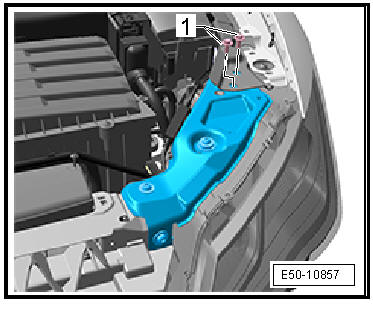
- Remove fuse -1-, press down in -the direction of the arrow- and disconnect the connector of the -2- crash sensor.
- Remove screws -1-.
- Unscrew the bolts -1- with their adjustment sleeve.
- Remove screws -2-.
- Remove screws -1-.
- Unscrew the screws -1- and attach the centre guide - T10093- on both sides.
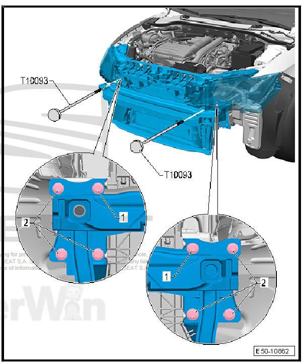
- Remove screws -2-.
| Caution Make sure that the paint of the longitudinal member or wing are not damaged. |
- Pull the lock carrier forwards.
- Install an adapter - T10467- on each side in the outer apertures of the longitudinal member. Press the adapter down using moderate pressure.
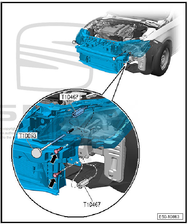
- Secure the lock member assembly. For this, install one of the previously inspected and approved screws in each of the threaded bores in the adapter-Arrows-. Tighten down the screws using moderate pressure.
fitting
Fit in reverse order from removal, remembering the following:
- Checking panel gaps.
- Perform basic setting of headlights, if installed.
Continuation only for vehicles with adaptive cruise control unit - J428-
- Calibrate adaptive cruise control.
 Removing and installing lock carrier
Special tools and workshop equipment required
Counterhold - T10038-
Centre guide - T10093-
Release lever - U30800-
Torque wrench - V.A.G 1331-
Release lever - 80 20 ...
 Lock carrier: replace
Special tools and workshop equipment required
Torque wrench - V.A.G 1331-
Remove lock carrier
Unscrew the bolts -arrow- with their adjusting sleeves. Subsequently
remove the main headl ...
See also:
Connection for external multimedia
devices
Removing and installing connection for
external audio source - R199-
Connection for external audio sources -
R199- : Removal and installation, in the
glove compartment
Special tools and workshop ...
