Seat Leon >> Dismantling and assembling output shaft
Special tools and workshop equipment required
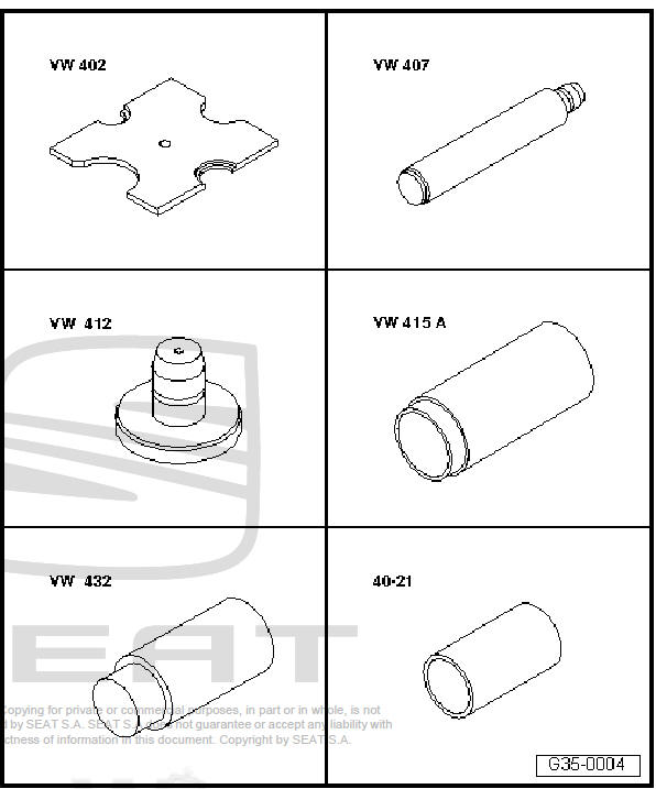
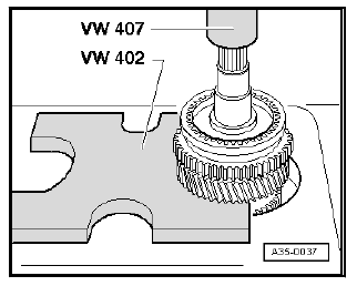
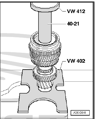
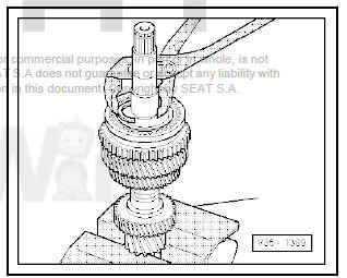
- Tightening plate - VW 402-
- Die - VW 407-
- Die - VW 412-
- Tube element - VW 415 A-
- Thrust pad - VW 432-
- Inlay socket - 30 - 100-
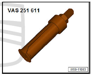
- Internal puller - VAS 251 611- or, e.g. internal puller - 1- Kukko 21/5-
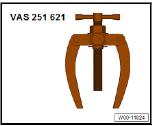
- Counter-support - VAS 251 621- or, e.g. counter-support - Kukko 22/1-
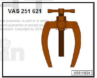
- Counter-support - VAS 251 621- or, e.g. counter-support - Kukko 22/1-
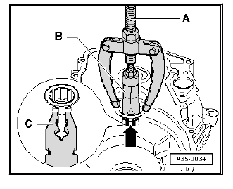
Pulling cylindrical roller bearing out of clutch housing
- When pulling out, squeeze together retaining ring -arrow- of cylindrical roller bearing, using pliers -C-.
- - Counter-support - VAS 251 621- or, e.g. counter-support - Kukko 22/1-
- - Internal puller - VAS 251 611- or, e.g. internal puller - Kukko 21/5-
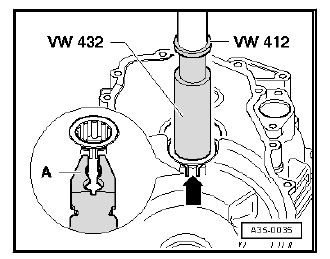
Extract the roller bearing from the clutch housing
- Support gearbox housing with tube - VW 415 A- (not visible in figure) directly below bearing support.
- When pressing in, compress circlip -arrow- for roller bearing using pliers -A-.
- Remove the pliers before the bearing is in its final installation position. The securing ring should insert into the groove of the clutch pan.
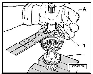
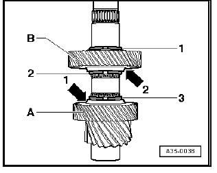
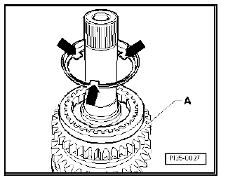
Press out securing ring -1- from its slot
- - Protective gloves
| WARNING Ensure retaining ring does not spring out uncontrolled. |
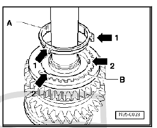
Press out the mobile sleeve / synchroniser body of 1st and 2nd gear
- After removing retaining ring, press off synchromeshed gear for 2nd gear together with locking collar and synchro-hub.
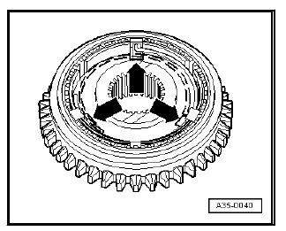
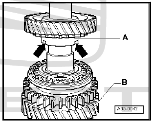
Installation position of 3rd gear and 4th gear
- Fit 4th gear wheel -A- onto output shaft.
Installation position:
The collar -arrow 1- should face towards the 3rd gear pinion -B-.
- Fit the securing rings -2- and -3-.
- Fit 3rd gear wheel -B- onto output shaft.
Installation position:
The collar -arrow 2- should face towards the 4th gear pinion -A-.
- Fit the securing ring -1-.
Check overall whether synchro-ring of the 1st and 2nd gear and inner ring are worn
- Press synchro-ring, outer race and inner ring onto cone of synchromeshed gear and measure gap -a- at three points displaced by approx. 120º using feeler gauge.
- Make a note of average value.
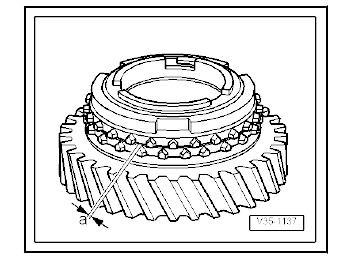
Note Always replace inner ring, outer ring and synchro-ring together.
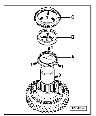
Installation position of the outer, inner and synchromesh rings for 2nd gear
- Fit the interior ring -A- onto the mobile pinion for 2nd gear.
Angled lugs -arrow 1- face outer ring -B-.
- Fit the outer ring -B-.
Lugs -arrow 2- engage in notches -arrow 3- of synchromeshed gear.
- Fit the synchroniser ring -C-.
The recesses -arrow 4- locate on the tabs -arrow 1- of the inner ring -A-.
Disassembly and assembly of the mobile element/synchroniser body for the 1st and 2nd gear
- - Spring
- - Mobile element
- - Synchromesh hub
- - Locking element
- The locking collar is fitted onto the synchro-hub.
Installation position:
After assembling the unit, the groove of the front part -arrow Aand the highest collar -arrow B- of the synchro-hub should face the exterior cogs of the locking collar -arrow C-.
The deeper grooves -arrow D- of the locking piece in the synchromesh must be aligned with the grooves -arrow E- of the mobile sleeve.
Assembling locking collar with synchro-hub for 1st and 2nd gears
- Locking collar has been pushed over synchro hub.
- Fit the locking elements in the deepest grooves -arrows- and fit the elastic rings off-set by 120º. Angled end of spring must locate in hollow locking piece.
Insert mobile element/synchroniser body of the 1st and 2nd gear
Installation position:
Groove in locking collar for selector fork faces 1st gear and teeth for reverse gear face 2nd gear.
- Turn the synchromesh ring so that the notches coincide with the locking elements.
Fitting retaining ring
- Fit the 1st gear securing ring on the mobile sleeve / synchromesh assembly.
Installation position of outer ring for 1st gear
The tabs -arrows- point towards the teeth of the reverse gear -A-.
Installation position of 1st gear inner ring -A-
The tabs -arrows 1- insert into the recesses -arrows 2- of the synchromesh ring -B-.
Installation position of synchromeshed gear for 1st gear
The highest collar -A- should face 2nd gear -B-. Notches in shoulder -arrows- engage in lugs of outer ring (-arrow-)
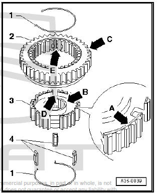
 Assembly overview - output shaft
Note
When installing new gears or new input shaft, refer to - Electronic
parts catalogue (ETKA) and technical
data.
Install all bearings, synchromeshed gears and synchro-rings on output
...

See also:
Removing and installing brake disc
Removing and installing brake disc,
brake caliper FS III
Special tools and workshop equipment required
Torque wrench 2-10 Nm - VAG 1783-
Removing:
Remove wheels.
Remove the brake pads ...
