Seat Leon >> Removing and installing drive shaft
Special tools and workshop equipment required
- Torque wrenches - V.A.G 1332-
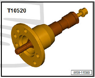
- Puller - T10520-
| Caution When removing and installing drive shafts, do not allow them to hang free and stop against joints due to excessive bending. |
Removing
- Loosen bolt securing drive shaft at wheel hub
| Caution Wheel bearings must not be subjected to load after loosening bolt securing drive shaft at wheel hub. If they have to support the weight of the vehicle they will be damages and their service life will be reduced. It is not permissible to turn drive shaft bolt more than 90º anticlockwise if vehicle is standing on its wheels. Do not attempt to move the vehicle without the drive shafts fitted; this would result in wheel bearing damage. If it is necessary for a vehicle to be moved, please comply with the following instructions:
|
- Remove rear wheel on affected side.
- Remove coil springs.
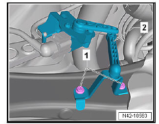
Vehicles with vehicle level senders
- Remove bolts -1-.
- Remove retainer for rear left vehicle level sender -2-.
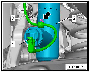
Vehicles with adaptive chassis control DCC
- Disconnect connector -1- on shock absorber -2-.
- Pull line -3- off shock absorber -2- -arrow-.
Note If there is moisture in the area of the connector, blow compressed air on the contacts on the shock absorber and the connector.
Vehicles with stone deflector
- Remove spreader rivets -1-.
- Remove bolts -2- for stone guard -3-.
Continuation for all models:
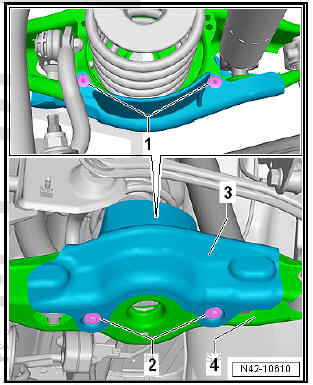
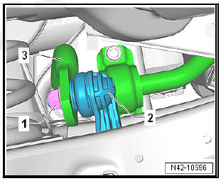
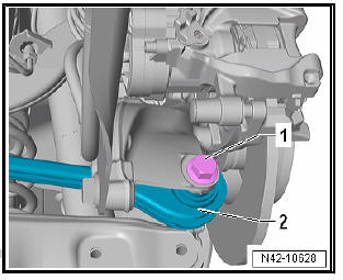
- Unscrew nut -1- securing coupling rod -2-.
- Pull coupling rod -2- out of anti-roll bar -3-.
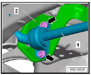
- Remove bolts -arrows- for anti-roll bar -1-.
- Pull anti-roll bar -1- off subframe -2- and swing it downwards.
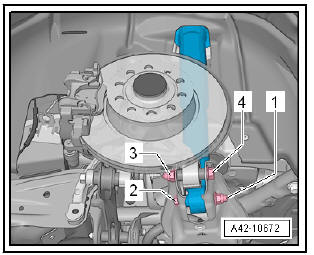
- Unscrew nut -1- and pull out bolt -2- securing shock absorber.
- Unscrew nut -3- and pull out bolt -4- securing wheel bearing housing.
- Unscrew bolt -1- for track rod -2- and remove.
- Unbolt drive shaft from gearbox flange.
- Swing wheel bearing housing outwards and pull drive shaft out of gearbox flange.
- Swing drive shaft downwards and remove from wheel bearing.
If the drive shaft cannot be pulled out of the wheel bearing by hand, use press tool - T10520- .
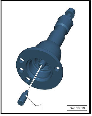
Before using press tool - T10520- ensure that thrust piece -1- is inserted.
Using press tool - T10520- :
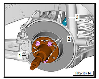
- To be able to press out the drive shaft -3-, secure press tool - T10520- -1- to the wheel hub -2- using 3 wheel bolts.
- It is essential to follow specified sequence.
I - Tighten knurled nut -1- hand-tight.
II - Turn only bolt -2- using a spanner in order to press out drive
shaft with press tool - T10520- .
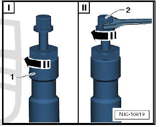
Note At the end of the procedure or for pressing out drive shaft further the spindle must be moved to its original position in order to deploy the hydraulic force!
- Remove drive shaft.
Installing
Carry out installation in the reverse sequence, noting the following:
- The threaded connections of the wheel bearing housing may only be loosened and tightened in the unladen weight position.
- On vehicles with vehicle level sender, carry out basic settings for wheel damper electronics - Vehicle diagnostic tester.
- Before fitting the outer joint in the wheel hub, apply a thin coat of assembly paste to the splines on the outer joint - Electronic parts catalogue "ETKA" .
Specified torques
- On vehicles with vehicle level sender, carry out basic adjustment of headlights.
 Assembly overview - drive shaft
- Outer constant velocity joint
Always replace completely
Removing
Installing: drive ontoshaft as far as stop usingplastic hammer
Distribute grease fillingevenly in joint
Checking ...
 Dismantling and assembling drive shaft
Special tools and workshop
equipment required
Tightening plate - VW 401-
Tightening plate - VW 402-
Die - VW 408 A-
Die - VW 411-
Tube element - VW 416 B-
Thrust pad - VW 447 H
...
See also:
Configure and check the Bluetooth connection
between the customer's mobile
telephone and the vehicle's hand-free system
It is necessary to configure the Bluetooth connection between the
mobile telephone and the hands-free system before it can be
used for the first time.
Certain software versions may not operate er ...
