Seat Leon >> Adaptive cruise control
Components of Adaptive Cruise Control
Fitting location overview - adaptive cruise control
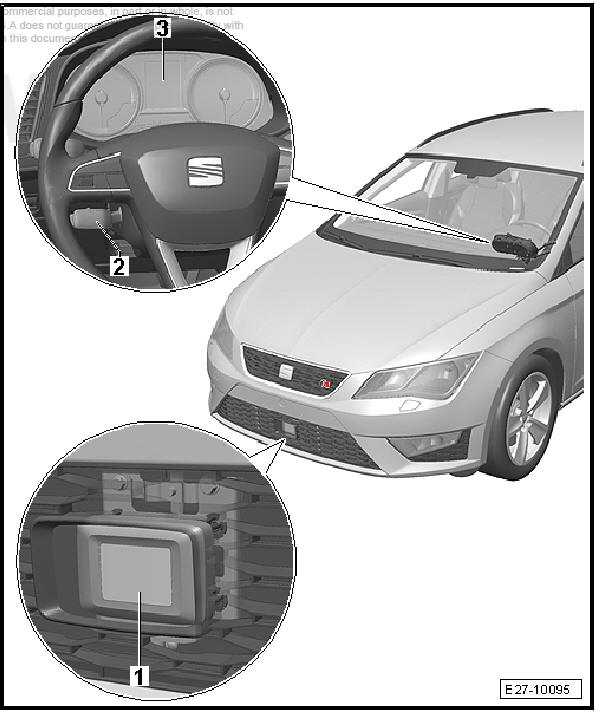
- - Adaptive cruise control unit
- J428-
- Assembly overview
- - ACC button - E357-
- Combined component with steering column switch module. Cannot be renewed individually.
- Switch module: remove and install
- - Instrument cluster - KX2-
- With control unit in dash panel insert - J285-
- Removal and installation
Removing and installing the automatic distance control unit
Special tools and workshop equipment required
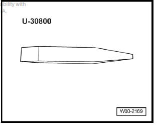
- Lever - U30800-
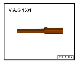
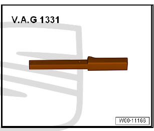
- Torque wrenches - VAG 1331-
Note For greater clarity the bumper grille is not depicted in the illustration.
Removing
- Switch off ignition and all electrical consumers.
Vehicles without access and start authorisation system
- Remove ignition key, if fitted.
Vehicles with access and start authorisation system
- Store the ignition key outside the vehicle to prevent the ignition from being switched on unintentionally.
Continued for all vehicles
- Removing trim for radar sensor.
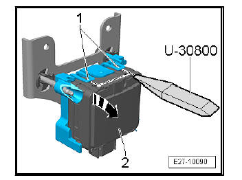
- Pull out the plug -2-.
- Prise out the securing tabs -1- with the aid of the lever - U30800- in order to free the centre nipple.
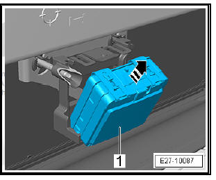
- Turn the adaptive cruise control unit - J428- -3- in the -direction of the arrow-.
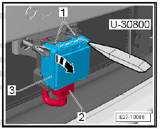
- Remove the adaptive cruise control unit - J428- -1- in the -direction of the arrow-.
Installing
Installation is carried out in the reverse sequence; note the following:
- Calibrate adaptive cruise control
Radar holder for the adaptive cruise control unit - J428- : remove and install
Special tools and workshop equipment required
- Calliper square - VAS 6335-
Note
- For greater clarity the bumper grille is not depicted in the illustration.
- Completely remove the adaptive cruise control unit assembly - J428- .
Removing
- Switch off ignition and all electrical consumers.
Vehicles without access and start authorisation system
- Remove ignition key, if fitted.
Vehicles with access and start authorisation system
- Store the ignition key outside the vehicle to prevent the ignition from being switched on unintentionally.
Continued for all vehicles
- Removing trim for radar sensor
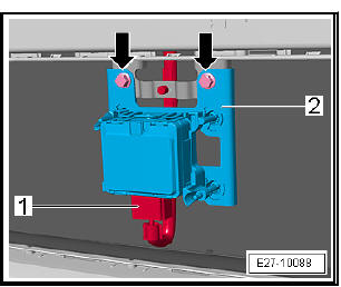
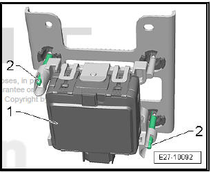
- Pull out the plug -1-.
- Unscrew bolts -arrows-.
- Lay the adaptive cruise control unit assembly - J428- -2- on a workbench.
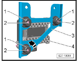
- Release the fasteners -1- in the -direction of the arrow-.
- Remove the fasteners -1- from the studs -2-.
- Remove the radar holder -3- from the assembly -4- adapter/ adaptive cruise control unit - J428- .
Installing
Installation is carried out in the reverse sequence; note the following:
Note
- Replace the fasteners -1-.
- The studs -1- on the adapter are pre-set. If necessary, adjust the setting.
Removing and installing trim for radar sensor
Special tools and workshop equipment required
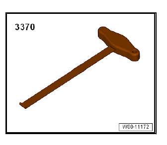
- Lever for the front-end - 3370-
Removing
- Switch off ignition and all electrical consumers.
Vehicles without access and start authorisation system
- Remove ignition key, if fitted.
Vehicles with access and start authorisation system
- Store the ignition key outside the vehicle to prevent the ignition from being switched on unintentionally.
Continued for all vehicles
- Insert the lever for the front end - 3370- in the side recess and pull not too strongly in the -direction of the arrow-.
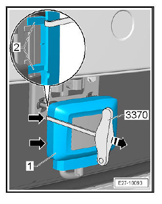
Note For greater clarity the bumper grille is not depicted in the illustration.
- Remove with the fixing lugs -2- on both sides.
Installing
Installation takes place in reverse order.
Settings of the studs on the adapter
Special tools and workshop equipment required
- Gauges for measuring spacing - VAS 6335-
In order to measure the adjustment dimension and be able to carry out adjustment the assembly adaptive cruise control unit assembly consisting of the following components - J428- must be fitted:
- Fasteners
- Radar holder
- Studs
- Adapters
- Adaptive cruise control unit - J428-
- Lay the adaptive cruise control unit assembly - J428- down on a soft and clean surface.
- With a sliding calliper measure - VAS 6335- the setting dimension
-a- on all studs and adjust if necessary.
- Setting dimension -a-= 68.2 mm
- Adjuster screws -2- of the adaptive cruise control unit - J428- -1-.
Remove and install adapter
Special tools and workshop equipment required
- Lever - U30800-
- Torque wrenches - VAG 1331-
- Calliper square - VAS 6335-
Removing
- Switch off ignition and all electrical consumers.
Vehicles without access and start authorisation system
- Remove ignition key, if fitted.
Vehicles with access and start authorisation system
- Store the ignition key outside the vehicle to prevent the ignition from being switched on unintentionally.
Continued for all vehicles
- Disconnect ignition and all electrical loads, and remove ignition key.
- Remove the radar holder for the adaptive cruise control unit - J428- .
- Prise out the securing tabs -1- with the aid of the lever - U30800- and move the adaptive cruise control unit - J428- -2- in -the direction of the arrow-.
- Remove the adaptive cruise control unit - J428- -2- from the adapter -1- in -the direction of the arrow-.
Installing
Installation is carried out in the reverse sequence; note the following:

Note
- Replace the fasteners .
- The studs on the adapter are pre-set. If necessary, adjust the setting.
Assembly overview - adaptive cruise control unit - J428-
Note For greater clarity the bumper grille is not depicted in the illustration.
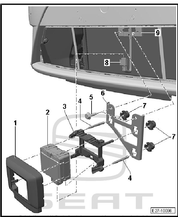
- - Cover
- Removal and installation
- - Adaptive cruise control unit
- J428-
- Removal and installation
- Calibrating
- - Adapter
- Removal and installation
- Measure adjustment and adjust if necessary
- - Threaded pins
- 2 units.
- If adjustment is completed, stud setting must not be changed anymore.
- Measure adjustment and adjust if necessary
- - Screw
- 2 units.
- 8 Nm
- - Radar holder
- Removal and installation
- - Mounting clips
- 3 units.
- Renew
- - Electric connector
- - Front bumper bracket
- On the front cross member
Calibrating adaptive cruise control
Requirements
- The adaptive cruise control unit - J428- needs to be calibrated
if the following conditions apply:
- Adaptive cruise control unit - J428- has been removed and then reinstalled or it has been renewed.
- Bumping into adaptive cruise control unit - J428- due to incautious installation of front bumper carrier.
- Damage to the front bumper carrier as a result of a front-end collision or similar.
- The front bumper carrier has been removed and then reinstalled or it has been renewed.
- Rear axle toe has been adjusted.
Note
- Excessive horizontal adjustment of the adaptive cruise control unit - J428- results in permanent deactivation of the functions ACC/front scan system. This is displayed in the dash panel insert - KX2- by the following message: ACC / Front Assist not available.
- Limited sensor functionality due to soiling or weather conditions such as heavy rain, snowfall, sensor icing etc. results in a temporary non-availability of the functions ACC/front scan system. This is displayed in the dash panel insert - KX2- by the following message: ACC / Front Assist: Sensor without view.
- Calibrate adaptive cruise control.
 Start-Stop System
General description - start/stop system
- Alternator
Removal and installation
- Onboard supply control unit
- J519-
Removal and installation
- Instrument cluster
Remov ...

See also:
Leaks at shock absorbers
Shock absorbers are often replaced because of externally visible
leakage. Inspections on the test rig and in the vehicle have shown
that in the majority of cases this replacement is not justified.
...
