Seat Leon >> Removing and installing brake servo
Removing and installing brake servo, LHD
Note If there are problems with the brake servo, first check the brake servo vacuum system
Special tools and workshop equipment required
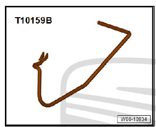
- Release tool - T10159 A- or
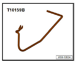
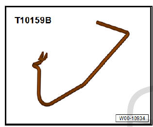
- Release tool - T10159 B-
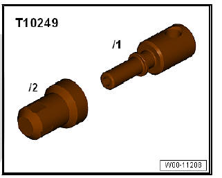
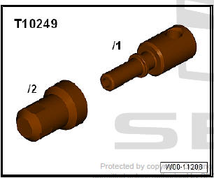
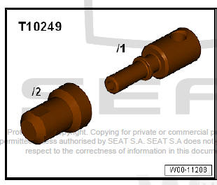
- Sealing tool - T10249-
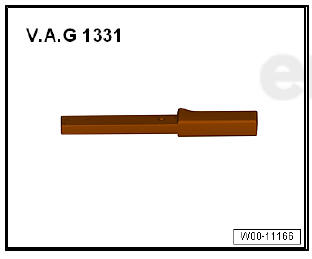
- Torque wrenches - V.A.G 1331-
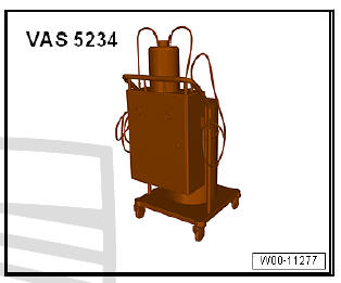
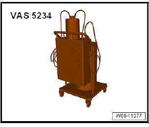
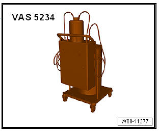
- Brake filling and bleeding equipment - VAS 5234-
Removing:
- Reduce the pressure in the servo brake by pressing on the brake pedal several times.
- Remove driver's side knee airbag and cover (depends on version).
- Remove battery and battery tray .
- Remove brake master cylinder with brake fluid reservoir.
- Disconnect vacuum line from brake servo and move to one side.
petrol engine vehicles
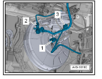
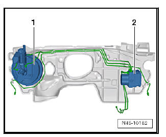
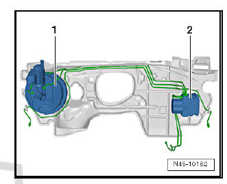
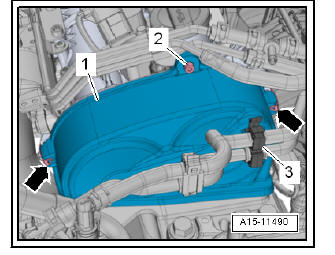
- Detach brake servo pressure sensor - G294- -2-.
Continued for all vehicles
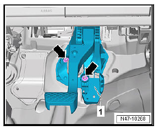
- Separate the brake pedal from the servo brake
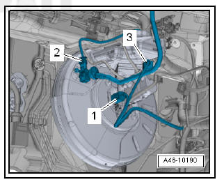
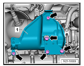
- Remove nuts for brake servo -3 and 4- on mounting bracket.
Note A heat shield is fitted on the brake master cylinder on some models.
- Note A heat shield is fitted on the brake master cylinder on some models.
Note
- The brake servo only has the additional adhesive bonding at the seal when originally installed at the factory.
- The adhesive bonding at the bulkhead/brake servo does not have to be renewed.
- Pull brake servo out of adhesive joint on bulkhead.
- Remove brake servo from vehicle.
- Remove remaining adhesive on bulkhead and brake servo.
Installation:
- Fit brake servo in vehicle.
Ensure that seal is seated correctly.
- Fit nuts.
- Tighten nuts for brake servo -3 and 4- on mounting bracket.
- Install the brake pedal in the brake force booster.
Note A heat shield is fitted on the brake master cylinder on some models.
- Install heat shield if previously removed.
- Press the vacuum line into the brake servo.
petrol engine vehicles
- Attach the brake servo pressure sensor - G294- -2-.
Continued for all vehicles
- Fitting the master cylinder.
- Install battery and battery tray .
- Install driver's side knee airbag and cover (depends on version).
- Bleed brake system .
Vehicles with clutch
- Bleeding clutch hydraulics system .
| Caution Before performing the first test drive, make sure that the brakes are operating correctly. |
Tightening torques:
- Tightening torques for heat shield nuts: 20 Nm
Removing and installing brake servo, RHD with diesel engine
Note If there are problems with the brake servo, first check the brake servo vacuum system
Special tools and workshop equipment required
- Release tool - T10159 A- or
- Release tool - T10159 B-
- Sealing tool - T10249-
- Torque wrenches - V.A.G 1331-
- Brake filling and bleeding equipment - VAS 5234-
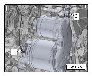
Fitting location of brake servo in RHD vehicles:
- - Brake servo and brake master cylinder
- - ABS hydraulic unit - N55- and ABS control unit - J104-
Removing:
- Reduce the pressure in the servo brake by pressing on the brake pedal several times.
- Remove brake master cylinder with brake fluid reservoir
- Disconnect vacuum line from brake servo and move to one side.
- Remove battery and battery tray .
- Remove the noise insulation.
- Remove door subframe together with steering box .
- Remove front exhaust pipe .
- Drain coolant .
- Remove left hand coolant pipes .
- Remove rear hand coolant pipe .
- Remove exhaust gas recirculation cooler .
- Remove exhaust gas temperature sender -1- and -2- .
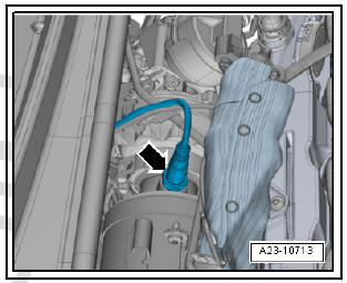
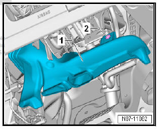
- Remove lambda probe -arrow- .
- Remove upper toothed belt cover.
- Remove emission control module .
Vehicles with air conditioning
- Drain air conditioning system .
- Remove coolant lines with internal heat exchanger .
Continued for all vehicles
- Remove the driver's side dash panel side cover .
- Remove driver's side footwell cover.
- Remove driver's side storage compartment.
- Remove the driver's side dash panel cover .
- Remove the knee airbag.
- Follow the safety precautions when carrying out tasks on the airbag.
- Remove the vent -1- in the footwell under the steering column.
- To do this, unscrew bolt -2- and remove footwell vent on driver side -1-.
- Unscrew the crash bar from the brake pedal and place it to one side .
- Separate the brake pedal from the servo brake.
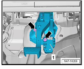
- Unscrew and remove the nuts -Arrows- from the bearing block.
- Remove brake booster downwards.
Installation:
Carry out installation in the reverse sequence, noting the following:
Note
- The brake booster only has the additional bonded joint at the seal when originally assembled at the factory.
- The adhesive bonding at the bulkhead/brake servo does not have to be renewed.
- Remove all remaining adhesive on bulkhead and, if necessary, on brake servo. Use adhesive strip remover - VAS 6349- and a drill, cordless screwdriver or grinder for this purpose.
- Let adhesive strip remover - VAS 6349- spread slowly over the processed surface, and rub it off the surface, working against running direction.
- Carefully insert brake servo and tighten nuts.
- When assembling brake master cylinder with brake servo, make sure plunger rod is properly positioned in brake master cylinder.
- When assembling brake master cylinder with brake servo, make sure seal is properly seated .
- Ensure that seals are correctly seated in brake master cylinder.
- Moisten sealing plugs with brake fluid before pressing brake fluid reservoir into brake master cylinder.
- Install the brake pedal in the brake force booster.
- Fill coolant.
- Bleed brake system.
Vehicles with manual gearboxes
- Bleed clutch control mechanism .
Vehicles with air conditioning
- Top up coolant.
Tightening torques:
- Crash bar
- Vent in the footwell under the steering column
- Driver's side covers
- exhaust gas temperature sender
- Front bleed valves
- Rear bleed valves
Removing and installing brake servo, brake pedal with 1.0-l, 1.2-l and 1.4-l petrol engine
Note If there are problems with the brake servo, first check the brake servo vacuum system
Special tools and workshop equipment required
- Release tool - T10159 A- or
- Release tool - T10159 B-
- Sealing tool - T10249-
- Torque wrenches - V.A.G 1331-
- Brake filling and bleeding equipment - VAS 5234-
Fitting location of brake servo in RHD vehicles:
- - Brake servo and brake master cylinder
- - ABS hydraulic unit - N55- and ABS control unit - J104-
Removing:
- Remove the noise insulation.
- Drain coolant .
- Remove catalytic converter -10- .
- Remove bracket -7-.
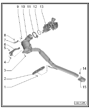
- Loosen hose clip -2- and remove coolant hose.
- Remove bolts -arrows- and swivel coolant lines -1- to right.
- Remove bolts -arrows-.
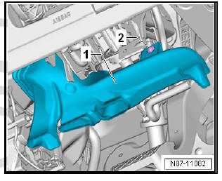
- Remove heat shield -1-.
- Screw out bolt -2-.
- Detach hoses from retainer -3-.
- Loosen clips -arrows- and remove upper toothed belt guard -1-.
- Reduce the pressure in the servo brake by pressing on the brake pedal several times.
- Remove brake master cylinder with brake fluid reservoir.
- Disconnect vacuum line from brake servo and move to one side.
- Remove the driver's side dash panel side cover .
- Remove driver's side footwell cover .
- Remove driver's side storage compartment.
- Remove the driver's side dash panel cover .
- Remove knee airbag.
- Follow the safety precautions when carrying out tasks on the airbag.
- Remove the vent -1- in the footwell under the steering column.
- To do this, unscrew bolt -2- and remove footwell vent on driver side -1-.
- Unscrew the crash bar from the brake pedal and place it to one side .
- Separate the brake pedal from the servo brake.
- Unscrew and remove the nuts -Arrows- from the bearing block.
Installation:
Carry out installation in the reverse sequence, noting the following:
Note
- The brake booster only has the additional bonded joint at the seal when originally assembled at the factory.
- The adhesive bonding at the bulkhead/brake servo does not have to be renewed.
- Remove all remaining adhesive on bulkhead and, if necessary, on brake servo. Use adhesive strip remover - VAS 6349- and a drill, cordless screwdriver or grinder for this purpose.
- Let adhesive strip remover - VAS 6349- spread slowly over the processed surface, and rub it off the surface, working against running direction.
- Carefully insert brake servo and tighten nuts.
- When assembling brake master cylinder with brake servo, make sure plunger rod is properly positioned in brake master cylinder.
- When assembling brake master cylinder with brake servo, make sure seal is properly seated .
- Ensure that seals .
- Moisten sealing plugs .
- Connect brake pedal to brake servo .
- Fill coolant .
- Bleed brake system.
Vehicles with manual gearbox:
- Bleed clutch control mechanism .
Vehicles with air conditioning:
- Top up coolant .
Tightening torques:
- Crash bar .
- Vent in the footwell under the steering column .
- Driver's side covers.
- Catalytic converter.
- Coolant lines on turbocharger.
- Air conditioning system.
- Front bleed valves.
- Rear bleed valves.
 Assembly overview - brake servo/brake
master cylinder
Assembly overview - brake servo/brake
master cylinder
Assembly overview - brake servo/brake
master cylinder, LHD
Note
The master brake cylinder and the servo brake can be replaced
independently.
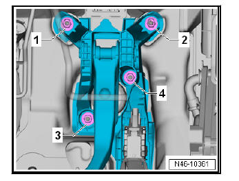
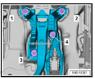
- Nut
Replace after each removal
23 Nm
...
 Removing and installing brake master
cylinder
Removing and installing brake master
cylinder
Removing and installing brake master
cylinder, LHD
Special tools and workshop equipment required
Torque wrenches - V.A.G 1331-
Brake filling and bleeding equipment - VAS 5234-
Remov ...
See also:
Starter motor: removing and installing
Installing and removing the starter, manual
transmission, gasoline engine
Special tools and workshop equipment required
Torque wrenches - VAG 1331-
Torque wrenches - VAG 1332-
Remov ...
