Seat Leon >> Exploded view - control unit and hydraulic unit
SEAT Leon Service and Repair Manual / Brake system / Anti-lock brake system / Control unit and hydraulic unit / Exploded view - control unit and hydraulic
unit
Exploded view - control unit and hydraulic unit, LHD
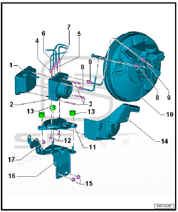
- - ABS control unit - J104-
- Do not unplug connector before completing self-diagnosis
- Switch off ignition before detaching connector
- - ABS hydraulic unit - N55-
- - Torx bolt
- Tighten the new Torx screws alternately in two stages:
- Stage 1: initial tightening torque: 1 Nm with 1.5 Nm (to allow the seal to settle)
- Stage 2: final specified torque: 2.5 Nm
- - Brake pipe
- To the rear right brake calliper
- Markings: Ø 5.25 mm and union nut with thread M 12 x 1
- 14 Nm
- - Brake pipe
- To front left brake caliper.
- Markings: Ø 5.25 mm and union nut with thread M 10 x 1
- 14 Nm
- - Brake pipe
- To front right brake caliper.
- Markings: Ø 5.25 mm and union nut with thread M 12 x 1
- 14 Nm
- - Brake pipe
- To the rear left brake calliper
- Markings: Ø 5.25 mm and union nut with thread M 10 x 1
- 14 Nm
- - Brake pipe
- Master brake cylinder / pressure-rod piston circuit to hydraulic unit
- Markings: Ø 6 mm and union nut with short thread M 12 x 1
- 14 Nm
- - Brake pipe
- From secondary piston circuit of brake master cylinder to hydraulic unit.
- Markings: Ø 6 mm and union nut with short thread M 12 x 1
- 14 Nm
- - Brake servo unit
- - Support
- - Torx bolt
- 8 Nm
- - Rubber damper
- 3 off
- - Heat shield
- Assignment - Electronic parts catalogue
- - Hexagonal nut
- 20 Nm
- - Support
- - Hexagonal nut
- 20 Nm
WARNING
Do not bend the brake lines.
Any damaged brake lines must be renewed.
Exploded view - control unit and hydraulic unit, RHD
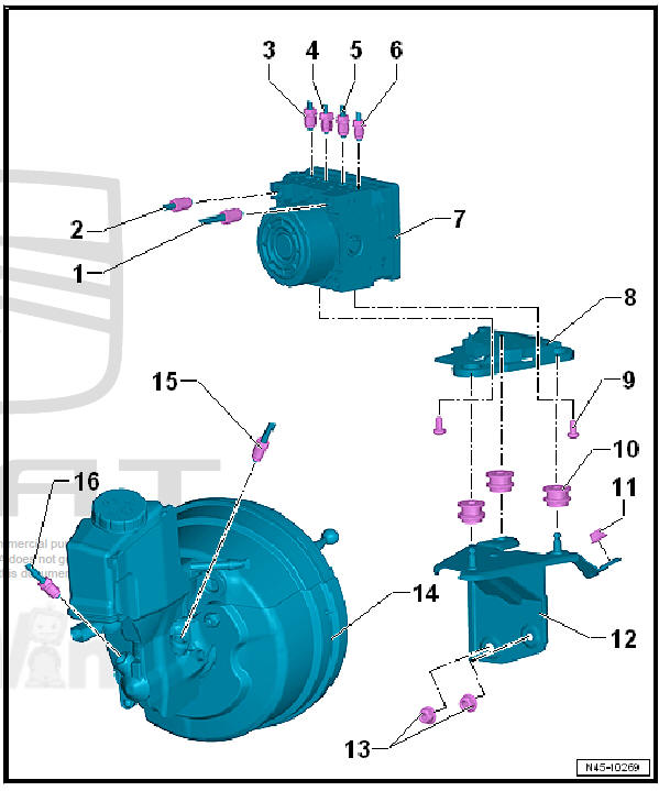
- - Brake pipe
- From secondary piston circuit of brake master cylinder to hydraulic unit.
- Markings: Ø 6 mm and union nut with short thread M 12 x 1
- 14 Nm
- - Brake pipe
- Master brake cylinder / pressure-rod piston circuit to hydraulic unit
- Markings: Ø 6 mm and union nut with short thread M 12 x 1
- 14 Nm
- - Brake pipe
- To the rear right brake calliper
- Markings: Ø 5.25 mm and union nut with thread M 12 x 1
- 14 Nm
- - Brake pipe
- To front left brake caliper.
- Markings: Ø 5.25 mm and union nut with thread M 10 x 1
- 14 Nm
- - Brake pipe
- To front right brake caliper.
- Markings: Ø 5.25 mm and union nut with thread M 12 x 1
- 14 Nm
- - Brake pipe
- To the rear left brake calliper
- Markings: Ø 5.25 mm and union nut with thread M 10 x 1
- 14 Nm
- - ABS hydraulic unit - N55- with ABS control unit - J104-
- - Support
- Check for secure seating after installing
- - Bolt
- 2 off
- 8 Nm
- - Rubber damper
- 3 off
WARNING
When installing the bracket, ensure that the rubber dampers are not pressed out of the console.
After installation, check that the ABS hydraulic unit - N55- is firmly seated, or malfunction can occur.
- - Nut
- 20 Nm
- - Support
- - Nut
- 2 off
- 20 Nm
- - Brake servo and brake master cylinder
- - Brake pipe
- Master brake cylinder / pressure-rod piston circuit to hydraulic unit
- Markings: Ø 6 mm and union nut with short thread M 12 x 1
- 14 Nm
- - Brake pipe
- From secondary piston circuit of brake master cylinder to hydraulic unit.
- Markings: Ø 6 mm and union nut with short thread M 12 x 1
- 14 Nm

 Removing and installing ABS control
unit - J104- / ABS hydraulic unit - N55-
Removing and installing ABS control
unit - J104- / ABS hydraulic unit - N55-
Removing and installing ABS control
unit - J104- / ABS hydraulic unit - N55- ,
left hand steering
Special tools and workshop
equipment required
Torque wrenches -
V.A.G 1331-
Torque w ...
See also:
Using these instructions
The vehicle includes a multifunction module from where it is possible to
control the audio, telephone and radio / navigation functions and the automatic
gearbox* without needing to distract the driv ...
