Seat Leon >> Removing and installing rear axle
Removing and installing rear axle, torsion beam axle
Special tools and workshop equipment required
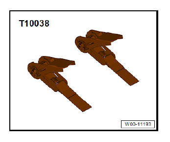
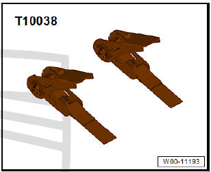
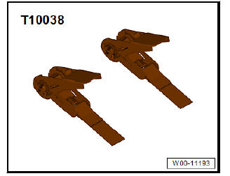
- Support tool - T10038-
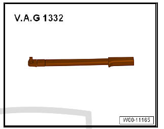
- Torque wrenches - V.A.G 1332-
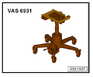
- Engine/gearbox jack - VAS 6931-
Removing
- Remove rear wheels.
- Release and pull off connector on rear left and right speed sensors .
- Unclip electrical wire from bracket on axle beam.
- Remove right and left brake calipers and hang on the body with wire .
Vehicles with electrical parking brake
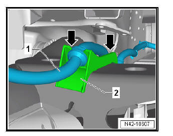
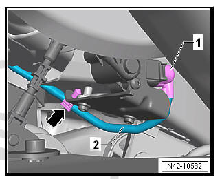
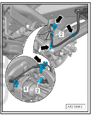
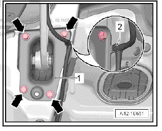
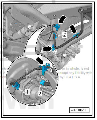
- Unclip electrical wire -1- from bracket -2- on axle beam (both sides) -arrows-.
Vehicles with manual parking brake
- Remove right and left brake cable.
Vehicles with vehicle level senders
- Release and pull off connector -1- on rear left vehicle level sender - G76- .
- Detach wire -2- from clip -arrow-.
Continuation for all models:
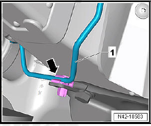
- Detach brake line -1- from clip -arrow- on mounting bracket (right-side).
Note The clip will be destroyed and must be renewed.
- Remove the coil springs.
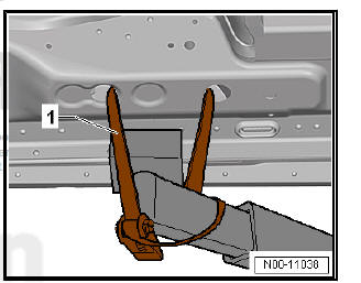
- Use tensioning straps - T10038- to strap vehicle to support beams of lifting platform on both sides.
| WARNING If the vehicle is not strapped down, there is a great danger that the vehicle will slip off the lifting platform! |
- Bring engine and gearbox jack - V.A.G 1383 A- into position.
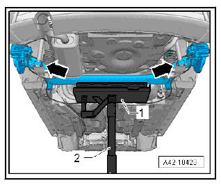
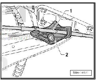
- Unclip electrical wiring -2- at mounting bracket -1- and axle beam and move clear.
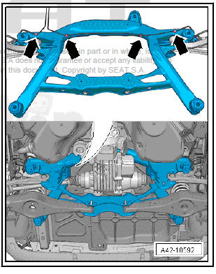
- Mark positions of bolts -arrows- on mounting bracket -1- on left and right sides of vehicle and remove them.
- Slightly take up weight of rear axle using engine and gearbox jack - V.A.G 1383 A- -1-.
- Unbolt rear axle from shock absorbers -arrows-.
- Lower subframe with the engine and gearbox jack - V.A.G 1383 A- or - VAS 6931- -1-.
- - Engine and gearbox jack - V.A.G 1383 A- or - VAS 6931-
- - Universal gearbox support - V.A.G 1359/2- (for engine and gearbox jack - V.A.G 1383 A- only)
Installing
Carry out installation in the reverse sequence, noting the following:
- Tighten bolted connection securing shock absorber to axle beam with suspension in unladen position.
Specified torques
- Bolts for brake caliper and brake disc.
- On vehicles with vehicle level sender, carry out basic settings for wheel damper electronics - Vehicle diagnostic tester
- On vehicles with vehicle level sender, carry out basic adjustment of headlights .
Removing and installing rear axle, multilink suspension, front-wheel drive
Special tools and workshop equipment required
- Support tool - T10038-
- Torque wrenches - V.A.G 1332-
Removing subframe with attachments
- Remove rear wheels.
- Unplug electrical connector -1- from ABS speed sensor on both sides and move clear.
Vehicles with electrical parking brake
- Disconnect the electrical connector -2-right and left of the engine of the electromechanical parking brake on the brake caliper.
Vehicles with manual parking brake
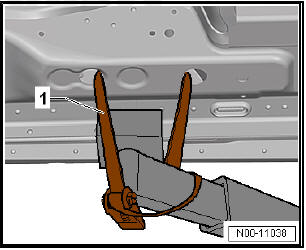
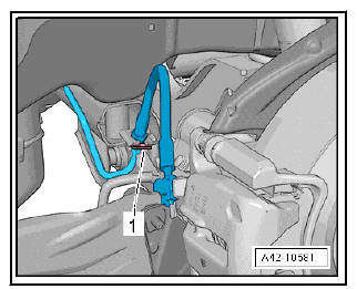
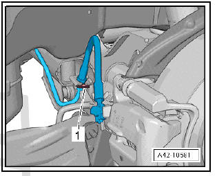
- First pull handbrake cable -1- off locking lugs, then pull completely out of bracket -2-.
- Detach electrical wiring harness from retainers -arrows- and move clear.
Vehicles with vehicle level senders
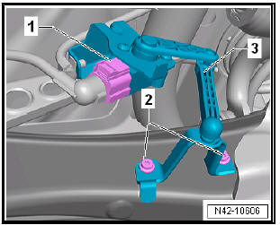
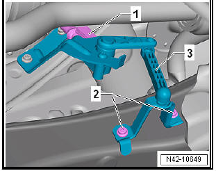
- Unplug the electrical connector -1-.
- Remove bolts -2-.
- Take rear left vehicle level sender - G76- -3- off transverse link.
Continuation for all models:
- Remove the coil springs
- Pull out retaining clip -1- on both sides of vehicle.
- Move brake line clear of retainer.
Note Do not open brake line.
- Remove right and left brake calipers and fasten to body with brake lines connected .
- Remove rear silencer for exhaust system .
- Use tensioning straps - T10038- to strap vehicle to support beams of lifting platform on both sides.
| WARNING If the vehicle is not strapped down, there is a great danger that the vehicle will slip off the lifting platform! |
- Locate subframe in position.
- Unclip electrical wire -2- on mounting bracket -1- and move clear.
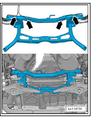
- Mark installation position of mounting bracket -1- on body.
- Remove bolts -arrows-.
- Carefully lower subframe with attachments a maximum of 30 mm.
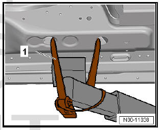
- Unclip brake line from clips -arrows-.
Note
- The clips will be destroyed and must be renewed.
- For reasons of clarity, the illustration shows the subframe from above in removed state.
- The number of clips may vary.
- Lower subframe with attached components.
Note When lowering, ensure sufficient clearance to brake lines and electrical wiring.
Installing subframe with attachments
Carry out installation in the reverse sequence, noting the following:
Specified torques
- Bolts for brake caliper and brake disc.
- Exhaust pipes double clamp.
- On vehicles with vehicle level sender, carry out basic settings for wheel damper electronics - Vehicle diagnostic tester.
- On vehicles with vehicle level sender, carry out basic adjustment of headlights.
Removing and installing rear axle, multilink suspension, four-wheel drive
Special tools and workshop equipment required
- Support tool - T10038-
- Torque wrenches - V.A.G 1332-
Removing subframe with attachments
- Remove rear wheels.
- Unplug electrical connector -1- from ABS speed sensor on both sides and move clear.
Vehicles with electrical parking brake
- Disconnect the electrical connector -2-right and left of the engine of the electromechanical parking brake on the brake caliper.
Vehicles with manual parking brake
- First pull handbrake cable -1- off locking lugs, then pull completely out of bracket -2-.
- Detach electrical wiring harness from retainers -arrows- and move clear.
Vehicles with vehicle level senders
- Unplug the electrical connector -1-.
- Remove bolts -2-.
- Take rear left vehicle level sender - G76- -3- off transverse link.
Continuation for all models:
- Remove the coil springs.
- Pull out retaining clip -1- on both sides of vehicle.
- Move brake line clear of retainer.
Note Do not open brake line.
- Detach propshaft from rear final drive and secure.
- Remove right and left brake calipers and fasten to body with brake lines connected .
- Remove rear silencer for exhaust system .
- Use tensioning straps - T10038- to strap vehicle to support beams of lifting platform on both sides.
| WARNING If the vehicle is not strapped down, there is a great danger that the vehicle will slip off the lifting platform! |
- Locate subframe in position.
- Unclip electrical wire -2- on mounting bracket -1- and move clear.
- Mark installation position of mounting bracket -1- on body.
- Remove bolts -arrows-.
- Lower subframe with attachments about 20 mm.
- Disconnect connector on all-wheel drive coupling above final drive.
- Carefully lower subframe with attachments 30 mm further.
Note When lowering, ensure sufficient clearance of brake lines, electrical cables and centring pin to propshaft.
- Detach brake line from clips -arrows- on both sides.
Note
- The clips will be destroyed and must be renewed.
- For reasons of clarity, the illustration shows the subframe from above in removed state.
- Carefully lower subframe with attachments.
Note When lowering, ensure sufficient clearance of brake lines, electrical cables and centring pin to propshaft.
Installing subframe with attachments
Carry out installation in the reverse sequence, noting the following:
Specified torques
- Propshaft .
- Bolts for brake caliper and brake disc .
- Exhaust pipes double clamp .
- On vehicles with vehicle level sender, carry out basic settings for wheel damper electronics - Vehicle diagnostic tester.
- On vehicles with vehicle level sender, carry out basic adjustment of headlights .
 Lowering rear axle
Lowering rear axle, multi-link suspension, front-wheel drive
Special tools and workshop
equipment required
attachment tool - 3301-
attachment tool - 3346-
Torque wrenches -
V.A.G 1332-
E ...
 Axle beam
Assembly overview - axle beam
- Cover
- Bolt
Always renew after removing
50 Nm +45º
- Bolt
Always renew after removing
Tighten in unladen state
70 Nm +360º
- A ...
See also:
Removing and installing coolant pipes
on heat exchanger
Removing and installing coolant pipes at
heat exchanger (Valeo)
Note
There are different designs and makes of heater and air conditioning
unit. The individual components of the various heaters and ...
