Seat Leon >> Heater unit
Assembly overview - heater unit
Note
- There are different designs and makes of heater. The individual components of the various heaters are similar but not identical. The combined fitting of different makes of component is therefore not permissible.
- The following illustrations show a "Valeo" heater, distinguishing features with respect to other brands.
Heater, flap control
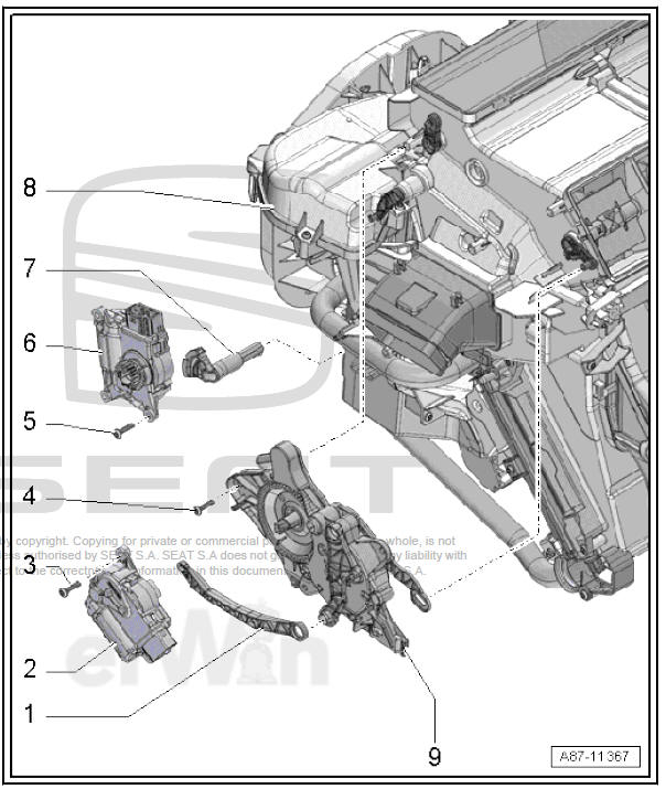
- - Operating lever
- For actuation of defrost and air distributor flap
- - Air distribution flap servomotor
- V428-
- With potentiometer for air distribution flap servomotor - G645- .
- Removing and fitting
- - Bolt.
- 2 off
- Tightening torque
- - Bolt.
- 3 off
- Tightening torque
- - Bolt.
- 2 off
- Tightening torque
- - Servomotor for temperature
flap - V68-
- With potentiometer for temperature flap control motor - G92-
- Removing and fitting
- - Operating lever
- For actuation of warm air flap
- - Heater unit
- Different versions
- The combined fitting of different makes of component is not permissible
- The following illustrations show the heater from "Valeo"
- The design is largely identical to that of the heater/air conditioning unit
- Components that are not installed: Expansion valve, condensation water drain, evaporator, etc.
- A honeycomb element is fitted instead of the evaporator
- There is no opening for the expansion valve in the plenum chamber back wall seal or this is closed off by a foam pad
- Assembly overview
- - Defroster and air distribution flap actuator
- Removing and fitting
Heater, heat exchanger, auxiliary air heater element
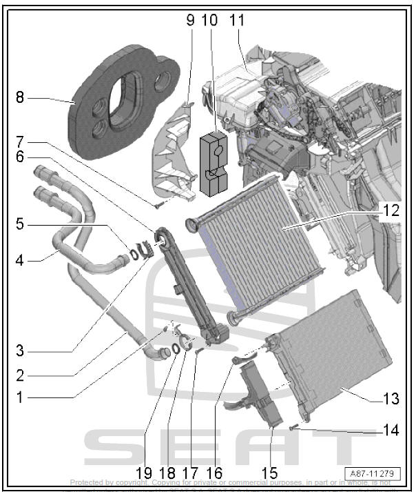
- - Bolt.
- Tightening torque
- - Coolant pipe for heat exchanger
- Removing and fitting
- - Staple
- - Coolant pipe for heat exchanger
- Removing and fitting
- - O ring
- - Cover
- For heat exchanger
- - Bolt.
- Tightening torque
- - Foam spacer
- - Support plate
- For coolant pipes
- - Foam rubber
- Note the fitting position
- - Heater unit
- Removing and fitting
- Dismantling and assembling
- - Heat exchanger
- Removing and fitting
- - Heating element for additional heater - Z35-
- Removing and fitting
- - Bolt.
- 2 off
- Tightening torque
- - Electrical wire
- For auxiliary air heater element - Z35-
- Removing and fitting
- - Negative wire
- For auxiliary heating.
- Tightening torque
- - Bolt.
- 3 off
- Tightening torque
- - Cable clip
- - O ring
Air intake housing, dust and pollen filter, fresh air blower, flap control
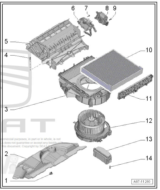
- - Bolt.
- 2 off
- Tightening torque
- - Cover
- - Top section of housing
- - Bolt.
- 2 off
- Tightening torque
- - Air intake housing
- Do not dismantle
- Removing and fitting
- - Not installed
- - Not installed
- - Servomotor for air recirculation
flap - V113-
- Removing and fitting
- - Bolt.
- 2 off
- Tightening torque
- - Dust and pollen filter
- Removing and fitting
- - Cover
- for dust and pollen filter
- - Fresh-air turbine - V2-
- Removing and fitting
- - Control unit for fresh air blower - J126-
- Removing and fitting
- - Bolt.
- 2 off
- Tightening torque
Removing and installing fresh air blower - V2-
Removal and installation are identical with procedure for vehicles with air conditioning system.
Removing and installing dust and pollen filter
Removal and installation are identical with procedure for vehicles with air conditioning system.
Removing and installing heat exchanger
Removal and installation are identical with procedure for vehicles with air conditioning system.
Removing and installing heater unit
Note The design of the heater is largely identical to that of the heater/ air conditioning unit. Components that are not installed: Expansion valve, condensation water drain, evaporator, etc.
Removal and installation are essentially the same as for the air conditioning unit.
Removing and installing supplementary air heater element - Z35-
Removal and installation are identical with procedure for vehicles with air conditioning system.
Dismantling and assembling heater unit
The heater dismantling and assembly operations are the same as for the heater/air conditioning unit of the manually controlled air conditioner.
Note The design of the heater is largely identical to that of the heater/ air conditioning unit. Components not installed: expansion valve, condensation water train, evaporator, etc. On the heating device, a honeycomb element is installed instead of the evaporator.
There is no opening for the expansion valve in the plenum chamber back wall seal or this is closed off by a foam pad.
 Fitting location overview - heating
Fitting location overview - components outside of passenger compartment
- Exhaust ventilation for passenger
compartment
Check
Removing and fitting
- exterior temperature sensor
...
 Servomotors
Fitting location overview - front servomotors
- Servomotor for temperature
flap - V68-
Removing and fitting
- Air distribution flap servomotor
- V428-
Removing and fitting
...
See also:
Wheel covers*
The wheel covers must be removed for access to the wheel
bolts
Removing
– Remove the wheel cover using the wire hook.
– Hook this into one of the cut-outs of the wheel cover.
Fitting
– Fit ...
