Seat Leon >> Removing and installing brake master cylinder
Removing and installing brake master cylinder, LHD
Special tools and workshop equipment required
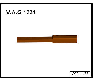
- Torque wrenches - V.A.G 1331-
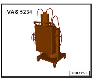
- Brake filling and bleeding equipment - VAS 5234-
Removing:
- Remove the brake fluid reservoir.
- Remove brake light switch - F-.
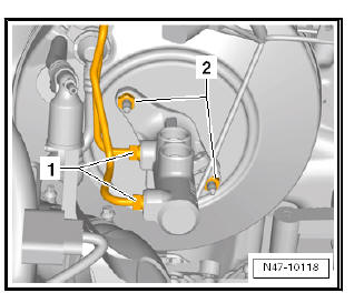
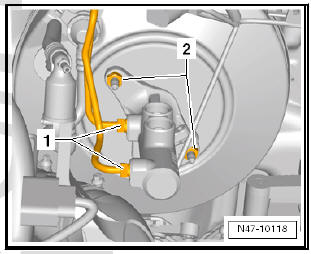
- Disconnect brake lines -1- from brake master cylinder and seal brake lines with plugs from repair kit.
- Unscrew securing nuts -2- for brake master cylinder.
Note A heat shield is fitted on the brake master cylinder on some models.
- Detach heat shield if fitted.
- Detach brake master cylinder from brake servo.
- Remove brake master cylinder from vehicle.
| Caution Brake fluid must not be allowed to enter the brake servo. |
Installation:
Note Before assembly, install the brake light switch - F- in the brake master cylinder.
- Install brake light switch - F-
| Caution Brake fluid must not be allowed to enter the brake servo. |
- Replace the seal between the brake master cylinder and the servo brake.
- When fitting the brake master cylinder, ensure that the control rod in the servo brake seats correctly.
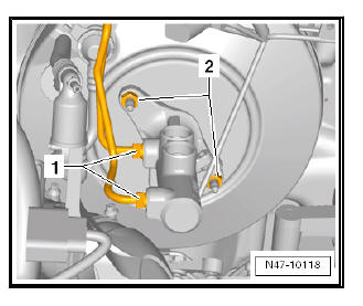
- Put on new nuts -2- and tighten to required torque.
Note A heat shield is fitted on the brake master cylinder on some models.
- Connect brake lines -1- to brake master cylinder. Note tightening torque.
- Install heat shield if previously removed.
- Connect the electric connector to the brake light switch - F- .
- Install brake fluid reservoir.
Note Plug in electrical connector for brake fluid level warning contact - -F34-- .
Note
- The brake light switch - F- does not have to be calibrated.
- Before the first journey, check that the brake light switch - F- is functioning without fault.
- Bleed brake system
Vehicles with clutch
- Bleeding clutch hydraulics system
Tightening torques:
- Tightening torques for heat shield nuts: 20 Nm
Removing and installing brake master cylinder; RHD
Note If there are problems with the brake servo, first check the brake servo vacuum system
Special tools and workshop equipment required
- Torque wrenches - V.A.G 1331-
- Brake filling and bleeding equipment - VAS 5234-
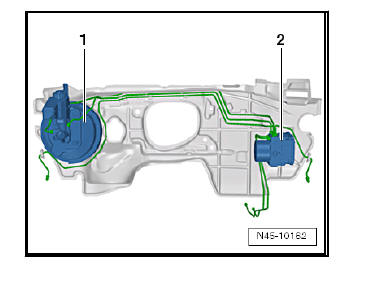
Fitting location of brake servo in RHD vehicles:
- - Brake servo and brake master cylinder
- - ABS hydraulic unit - N55- and ABS control unit - J104-
Removing:
- Remove brake light switch - F-
Vehicles with air conditioning
- Drain air conditioning system .
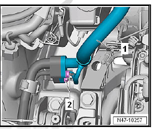
- Unscrew nuts -2- on refrigerant line -1-.
- Remove refrigerant line -1-.
Continued for all vehicles
- Remove the brake fluid reservoir.
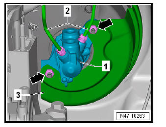
- Removing brake lines -2- on master brake cylinder -1-.
- Seal brake pipes with sealing plugs from repair kit Part No. 1H0 698 311 A.
- Unscrew nuts - arrows -.
- Remove heat shield -3-.
- Carefully remove brake master cylinder from brake servo.
Installation:
Carry out installation in the reverse sequence, noting the following:
- When assembling brake master cylinder with brake servo, make sure plunger rod is properly positioned in brake master cylinder.
- When assembling brake master cylinder with brake servo, make sure seal is properly seated.
- Ensure that seals are correctly seated in brake master cylinder.
- Moisten sealing plugs with brake fluid before pressing brake fluid reservoir into brake master cylinder.
- Bleed brake system
Vehicles with manual gearboxes
- Bleed clutch control mechanism .
Vehicles with air conditioning
- Top up coolant .
Tightening torques:
- Front bleed valves
- Rear bleed valves
 Removing and installing brake servo
Removing and installing brake servo,
LHD
Note
If there are problems with the brake servo, first check the brake
servo vacuum system
Special tools and workshop equipment required
Release tool ...
 Removing and installing brake fluid reservoir
Removing and installing brake fluid reservoir,
left-hand drive vehicle
Special tools and workshop equipment required
Sealing tool - T10249-
Brake filling and bleeding equipment - VAS 523 ...
See also:
Removing and installing actuator
Special tools and workshop equipment required
Torque wrench - V.A.G 1331-
Removing
Open the tailgate.
Remove lower tailgate trim.
Detach connector -4-.
Loosen nut -3-.
Turn the re ...
