Seat Leon >> Removing and installing ABS control unit - J104- / ABS hydraulic unit - N55-
Removing and installing ABS control unit - J104- / ABS hydraulic unit - N55- , left hand steering
Special tools and workshop equipment required
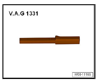
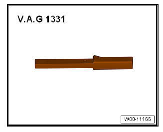
- Torque wrenches - V.A.G 1331-
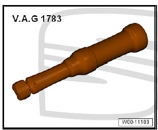
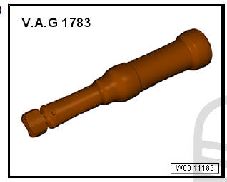
- Torque wrench 2-10 Nm - VAG 1783-
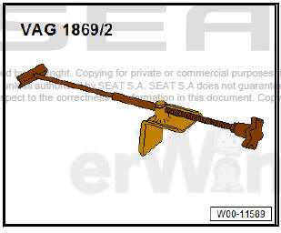
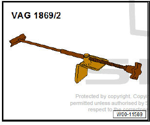
- Brake pedal depressor - V.A.G 1869/2-
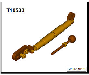
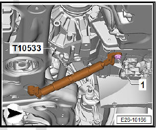
- Engine support - T10533- (only diesel vehicles with particulate filter)
- Wrench - VAS 5412-
- Vehicle diagnosis tester
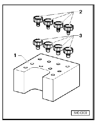
Sealing plug repair kit, Part no. 1H0 698 311 A
- - Valve dome transport protection (rubber foam).
- - M10 plug stop.
- - M12 sealing plugs.
Note
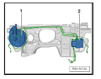
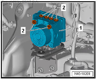
- The ABS control unit - J104- is bolted to the ABS hydraulic unit - N55- and located at the front right of the engine compartment.
- Remove ABS control unit - J104- of ABS hydraulic unit - N55-.
- Connect ABS control unit - J104- of ABS hydraulic unit - N55-.
WARNING
Do not bend the brake lines in the area of the hydraulic unit! Any damaged brake lines must be renewed.
Removing:
- Check and note the code for the control unit fitted.
- Disconnect battery .
- Remove engine cover.
Vehicles with diesel engine and four-wheel drive:
- Unbolt propshaft from front of bevel box.
For vehicles with diesel engine and particulate filter:
- Remove front exhaust pipe.
- Remove pendulum support.
- Fit engine support - T10533- as shown, tighten bolts manually.
Bolt -1- = original bolt for pendulum support.
- Shift engine and gearbox forwards as far as possible by turning the spindle. Avoid collisions.
Continuation for all models:
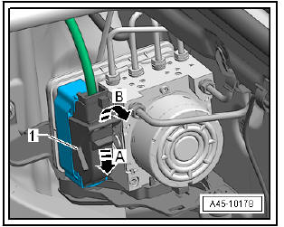
- Undo the clamp on the underside of the cover -arrow A- and remove to the side -arrow B-.
Note The cover is not fitted on all models.
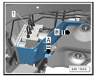
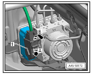
- Press down retainer catch -arrow A-.
- Release electrical connector -arrow B-.
- Unplug electrical connector -1-.
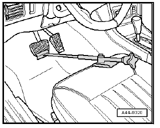
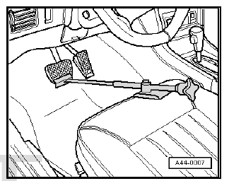
- Fit the block for the brake pedal - V.A.G 1869/2- .
- Depress brake pedal at least 60 mm using brake pedal depressor - V.A.G 1869/2- .
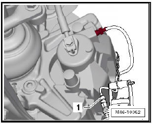
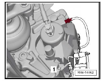
- Connect bleed bottle bleed hose -1- to bleed valve of front left brake caliper.
- Open bleed valve.
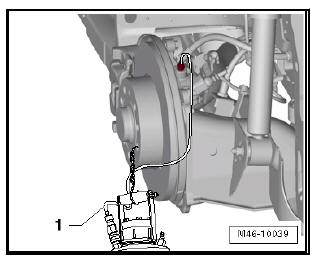
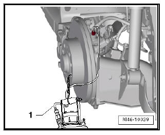
- Connect bleed hose of bleed bottle to bleed valve of rear left wheel brake cylinder.
- Open bleed valve.
- Close the front and rear left bleeding screws.
- Place a sufficiently large lint-free cloth under the control unit and the hydraulic unit.
| Caution Make sure that brake fluid does not fall onto the connectors. |
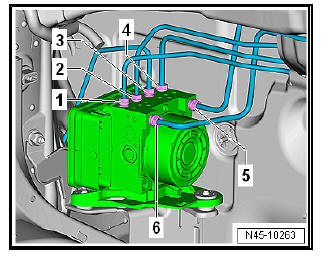
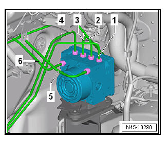
- Mark the brake lines on the hydraulic unit for ABS - N55- to the brake callipers and to the master cylinder.
- Unscrew retaining screws for the brake lines in the sequence -6...1-; slide brake lines slight to one side.
- Seal brake lines and threaded holes immediately using sealing plugs from repair kit - 1H0 698 311 A- .
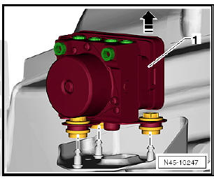
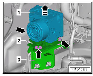
- Pull ABS hydraulic unit - N55- -1- together with ABS control unit - J104- and bracket upwards in -direction of arrow- off welded studs.
Note Do not remove the block for the brake pedal - V.A.G 1869/2- .
Vehicles with petrol engine:
- Remove ABS hydraulic unit - N55- with the ABS control unit - J104- upwards.
Diesel engine vehicles:
- Carefully set down ABS hydraulic unit - N55- together with the ABS control unit - J104- in engine compartment.
| Caution Place ABS hydraulic unit - N55- with ABS control unit - J104- so that it cannot fall. |
- Take out ABS hydraulic unit - N55- with the ABS control unit - J104- through the exhaust pipe tunnel opening.
Replacing the control unit:
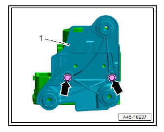
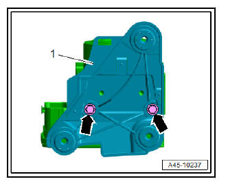
- Unscrew bolts -arrows- and remove bracket -1-.
| Caution The pump motor must not be unbolted from the hydraulic unit. |
Note
- Only the ABS control unit may be renewed separately - J104- .
- It is permissible to fit a new ABS control unit - J104- to the existing hydraulic unit.
- It is not permissible to fit the existing ABS control unit - J104- to a new hydraulic unit.
- If the ABS hydraulic unit - N55- is defective, it must always be renewed together with the ABS control unit - J104- .
Installation:
Carry out installation in the reverse sequence, noting the following:
- Screw the bracket -1- onto the hydraulic unit. Note tightening torque.
- Press ABS hydraulic unit - N55- with ABS control unit - J104- and bracket onto studs.
Note The ABS hydraulic unit - N55- with the ABS control unit - J104- must be seated on all the studs.
Note
- Remove sealing plugs from new hydraulic unit only when the corresponding brake line is to be fitted.
- If sealing plugs are removed too early from the hydraulic unit, brake fluid can escape, and it can then no longer be guaranteed that the unit can be sufficiently filled and bled.
- When installing the hydraulic unit, ensure that the rubber dampers are not pressed out of bracket. The rubber dampers must rest on the longitudinal member cover plate.
- Insert all brake lines in ABS hydraulic unit - N55- and fit threaded unions.
- Tighten all brake line connections on ABS hydraulic unit - N55- to specified torque.
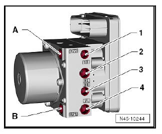
Markings on hydraulic unit:
- Screw the brake line tight.
- - Hydraulic unit to brake master cylinder (primary piston circuit), -HZ2-
- - Hydraulic unit to brake master cylinder (secondary piston circuit), -HZ1-
- - Hydraulic unit to front right brake caliper, -VR-
- - Hydraulic unit to rear left brake caliper / wheel brake cylinder, -HL-
- - Hydraulic unit to rear right brake caliper/wheel brake cylinder, -HR-
- - Hydraulic unit to front left brake caliper, -VR-
Component
- Bracket to ABS unit
- Brake lines to ABS unit
Fit cover of the hydraulic unit in place.
Note The cover is not fitted on all models.
- Install pendulum support .
- Screw propshaft onto front of bevel box.
- Remove front exhaust pipe .
- Remove the block for the brake pedal - V.A.G 1869/2- .
- Bleed brake system.
- If ABS control unit - J104- is being renewed, start appropriate program in "Guided Functions" - Vehicle diagnostic tester.
| Caution Before performing the first test drive, make sure that the brakes are operating correctly. |
Removing and installing ABS control unit - J104- / ABS hydraulic unit - N55- , right hand steering
Special tools and workshop equipment required
- Torque wrenches - V.A.G 1331-
- Torque wrench 2-10 Nm - VAG 1783-
- Brake pedal depressor - V.A.G 1869/2-
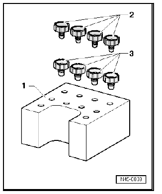
Cap - 1H0 698 311 A-
2 - Sealing plug M 10
3 - Sealing plug M 12
Fitting location of ABS hydraulic unit - N55- and ABS control unit - J104- in RHD vehicles:
- - Brake servo and brake master cylinder
- - ABS hydraulic unit - N55- and ABS control unit - J104-
Removing:
| WARNING Do not bend the brake lines in the area of the hydraulic unit! |
- Check and note the code for the control unit fitted.
- Remove battery and battery tray .
- Fit the block for the brake pedal - VAG 1869/2- .
- Remove the noise insulation .
- Press down retainer catch -arrow A-.
Note The illustration shows installation position of ABS hydraulic unit - N55- and ABS control unit - J104- on a LHD vehicle.
- Release electrical connector -arrow B-.
- Unplug electrical connector -1-.
- Connect bleed bottle bleed hose -1- to bleed valve of front left brake caliper.
- Open bleed valves.
- Connect bleed hose of bleed bottle -1- to bleed valve of rear left brake caliper.
- Open the bleeder valve.
- Depress brake pedal at least 60 mm using brake pedal depressor - V.A.G 1869/2- .
- Close the front and rear left bleeding screws.
- Do not remove the block for the brake pedal - VAG 1869/2- .
- Place sufficiently lint-free cloths under ABS control unit - J104- and ABS hydraulic unit - N55- .
| WARNING Make sure no brake fluid gets onto electrical contacts on ABS control unit - J104- . |
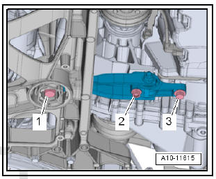
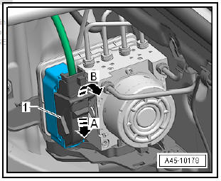
- First, mark the two brake lines -A- and -B- coming from brake master cylinder.
- Disconnect the two brake master cylinder brake lines -A- and -B- from ABS hydraulic unit - N55- .
- Immediately seal brake lines and threaded holes with seal plugs from repair set Part No. 1H0 698 311 A.
- Mark, disconnect and seal remaining brake lines -1- to -4-.
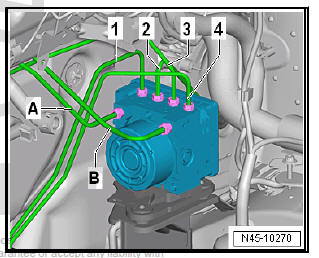
- Seal threaded holes of ABS hydraulic unit - N55- -1- using sealing plugs - 1H0 698 311 A- -2-.
- Pull off ABS hydraulic unit - N55- -1- together with bracket -2- in -direction of arrow-.
- The rubber dampers -arrows- will be pulled off the studs of the bracket -3-.
- Thread hydraulic unit out of vehicle.
Installation:
Carry out installation in the reverse sequence, noting the following:
Note
- Do not remove the anti-humidity plugs until fitting the corresponding brake lines.
- If the plugs are removed from the control unit beforehand, brake fluid may leak out, and therefore the fluid level and bleeding will be incorrect.
- Do not bend the brake lines in the area of the ABS hydraulic unit - N55-
- When installing the bracket, ensure that the rubber dampers are not pressed out of the console. After installation, check that the ABS hydraulic unit - N55- is firmly seated, or malfunction can occur.
Tightening sequence of brake lines:
- Start brake line union screws in sequence -1- through -6-.
- Tighten break line union screws in sequence -1- through -6-.
- Remove the block for the brake pedal - VAG 1869/2- .
- Bleed brake system.
- Code ABS control unit -J104- using - Vehicle diagnostic tester.
To do this, carry out basic setting of the steering angle sender - G85- , the lateral acceleration sender - G200- , the longitudinal acceleration sender - G251- and the brake pressure sender - G201- .
Tightening torques:
- Front bleed valves
 Exploded view - control unit and hydraulic
unit
Exploded view - control unit and hydraulic
unit
Exploded view - control unit and hydraulic unit, LHD
- ABS control unit - J104-
Do not unplug connector
before completing
self-diagnosis
Switch off ignition before
detaching conne ...
 Connecting brake lines to hydraulic unit
Connecting brake lines to hydraulic unit,
LHD
On the tandem master cylinder:
- Primary piston circuit of brake master cylinder to hydraulic unit.
Markings: Ø 6 mm and union nut with short th ...
See also:
Categorisation of child seats into groups
Use only child seats that are officially approved and suitable
for the child.
Child seats are covered by the European standard ECE R 44 (issued by the
Economic Commission of Europe).
The child s ...
