Seat Leon >> Removing and installing heat exchanger
Heat exchanger: removing and installing; manufacturer, Valeo
Note There are different designs and makes of heater and air conditioning unit. The individual components of the various heaters and air conditioning units are similar but not identical. The combined fitting of different makes of component is therefore not permissible.
Special tools and workshop equipment required
- Engine bung set - VAS 6122-
- Commercially available compressed-air gun
Removal:
- Set the air outflow direction to "defroster vent" for windscreen.
- Move front seat to rearmost position.
- Turn off the ignition and all electricity consumers.
Vehicles without access and start authorisation system
- Remove ignition key, if fitted.
Vehicles with access and start authorisation system
- Store ignition key outside the vehicle to prevent the ignition from being switched on unintentionally.
Continued for all vehicles
- Disconnect battery.
| WARNING Hot steam/hot coolant can escape - risk of scalding.
|
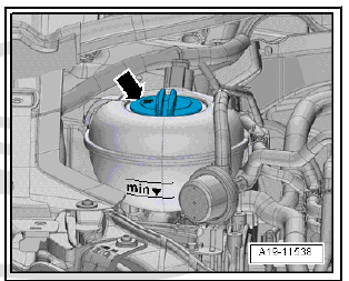
- Open cap -arrow- on coolant expansion tank.
Vehicles with petrol engine:
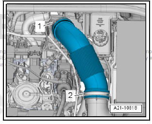
- Release hose clips -1- and -2- and remove air intake pipe.
Diesel engine vehicles:
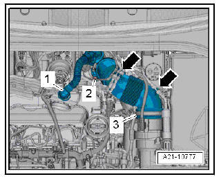
- Press the release buttons at the crankcase breather hose -1- and detach the hose from the cylinder head cover.
- Lay bare the vacuum hoses at the air pipe -arrows-.
- Release hose clip -3-.
- Screw out the bolt -2-, swivel the air pipe with connection to the rear and detach from the turbocharger.
All vehicles (continued):
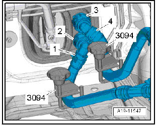
- Mark installation position of coolant hoses -1- and -4-.
Note The heat exchanger is designed for a certain coolant flow direction.
The coolant hoses must therefore be connected on the correct sides.
- Pinch off the coolant hoses with hose clamps -3094- .
- Lift the fasteners -2- and -3-, and detach the coolant hoses from the heating system heat exchanger.
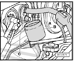
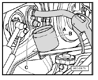
- Fit a short hose -A- to the upper connection.
Insert the compressed air gun in the end of the hose.
- Hold a collector -B- under the lower connection -C- and use the compressed air gun to carefully blow the coolant out of the heat exchanger.
- Seal open lines and connections with clean plugs from the Engine sealing plug set - VAS 6122- .
- Remove knee airbag on driver's side.
- Remove the side trim of the centre console and the lower dash panel trim.
Vehicles with supplementary air heater
- Separate the plug from the heater element for supplementary air heater - Z35-.
All vehicles (continued):
- Cover the area beneath the connections for the coolant hoses in the plenum chamber with impermeable sheeting and absorbent paper, for example.
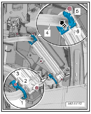
- Lift the locking element -6-, remove the clip -5- and detach the coolant line at the top -4- from the heat exchanger.
- Unscrew the bolt -3-.
- Remove the screw-type clamp -2- and detach the coolant line at the bottom -1- from the heat exchanger.
- Seal open lines and connections with clean plugs from the Engine sealing plug set - VAS 6122- .
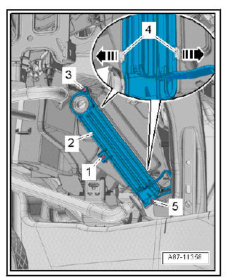
- Remove bolts -1, 3, 5-.
- Release the retainer tabs -4- -arrows- and detach the cover -2-.
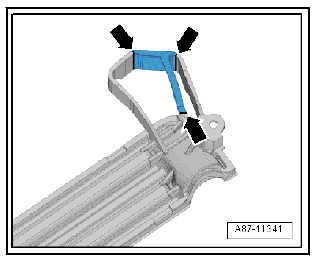
- Sever the tab at the cover -arrows-.
- Take out the heat exchanger to the left.
Installing
Install in reverse order of removal; note the following.
Note Replace the O-rings .
- Check the heater slot for contamination with the heat exchanger removed.
- Remove any dirt or residual coolant.
- Vehicles with diesel engine: with mounted heater element for supplementary air heater, check if the opening of the heating element is soiled and clean if necessary.
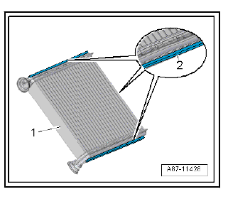
- Check the foam seals -2- attached to the heat exchanger -1- for damage and replace if necessary.
Note
- The foam seal may curl up on insertion if not correctly bonded on.
- Cold air may flow past the heat exchanger if the foam seal is damaged or not properly fitted.
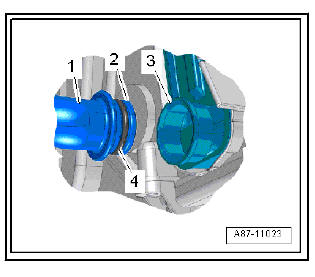
- Check connection -3- of the heat exchanger and connection -2- of the coolant pipes for damage or contamination.
- Clean and smooth sealing surface for O-ring.
- Moisten the new O-ring -4- with coolant (or lubricate lightly with silicone grease) and attach to the coolant pipe -1-.
- Carefully slide home the heat exchanger in the heater/air conditioning unit.
Note On inserting the heat exchanger, take care not to damage the connections and coolant pipes.
| Caution Risk of leaks at heat exchanger.
|
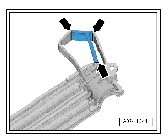
- Insert the cover of the heat exchanger at the front first.
- If the cover cannot be attached to the heat exchanger, cuts must be made at the rubber support -arrows- as shown.
- Slide coolant pipes into heat exchanger as far as stop.
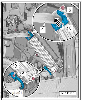
- Fit a new clip -5- or screw-type clamp -2- at the coolant pipe / heat exchanger joint.
Note
- When performing repairs, a screw-type clamp can also be fitted instead of the clip -5-.
- -Arrow- can be disregarded.
- Tighten bolt -3-.
- Check that screw-type clips are seated correctly on connections of heat exchanger and coolant pipes. They must not make contact with air distribution housing or other components.
- Fill coolant.
Heat exchanger: removing and installing, manufacturer, Denso
Note There are different designs and makes of heater and air conditioning unit. The individual components of the various heaters and air conditioning units are similar but not identical (distinguishing features). The combined fitting of different makes of component is therefore not permissible.
Special tools and workshop equipment required
- Engine bung set - VAS 6122-
- Pincers - T40147-
- Commercially available compressed-air gun
Removal:
- Set the air outflow direction to "defroster vent" for windscreen.
- Move front seat to rearmost position.
- Turn off the ignition and all electricity consumers.
Vehicles without access and start authorisation system
- Remove ignition key, if fitted.
Vehicles with access and start authorisation system
- Store ignition key outside the vehicle to prevent the ignition from being switched on unintentionally.
Continued for all vehicles
| WARNING Hot steam/hot coolant can escape - risk of scalding.
|
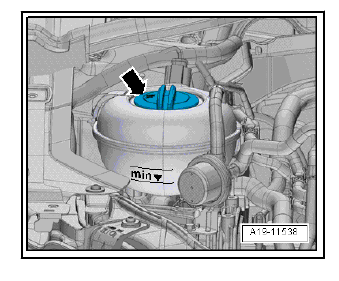
- Open cap -arrow- on coolant expansion tank.
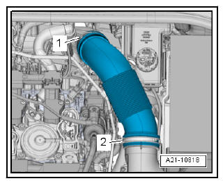
Vehicles with petrol engine:
- Loosen hose clips -1, 2- and remove air pipe.
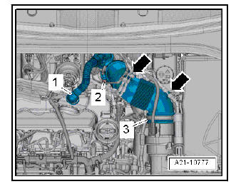
Diesel engine vehicles:
- Press the release buttons at the crankcase breather hose -1- and detach the hose from the cylinder head cover.
- Lay bare the vacuum hoses at the air pipe -arrows-.
- Release hose clip -3-.
- Screw out the bolt -2-, swivel the air pipe with connection to the rear and detach from the turbocharger.
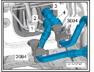
All vehicles (continued):
- Mark the installation position of the coolant hoses -1, 4-.
Note The heat exchanger is designed for a certain coolant flow direction.
The coolant hoses must therefore be connected on the correct sides.
- Pinch off the coolant hoses with hose clamps -3094- .
- Lift the fasteners -2, 3- and detach the coolant hoses from the heating system heat exchanger.
- Fit a short hose -A- to the upper connection.
- Insert the compressed air gun in the end of the hose.
- Hold a collector -B- under the lower connection -C- and use the compressed air gun to carefully blow the coolant out of the heat exchanger.
- Seal open lines and connections with clean plugs from the Engine sealing plug set - VAS 6122- .
- Remove knee airbag on driver's side.
- Remove the side trim of the centre console and the lower dash panel trim.
- Vehicles with supplementary air heater element: disconnect electrical connector.
- Cover the area beneath the connections for the coolant hoses in the plenum chamber with impermeable sheeting and absorbent paper, for example.
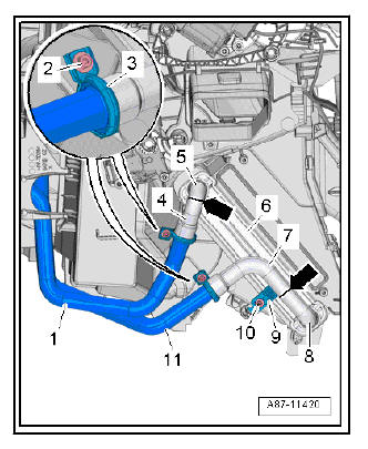
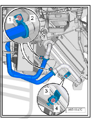
- Screw out the bolts -2- and detach the screw-type clamps -3-.
- Separate the coolant pipes.
Note
- If they cannot be separated as the O-ring is gummed up, cut through the coolant pipes at the marked locations -arrows-using pliers - T40147- .
- Bend the rest of the coolant pipes -5, 8- at the heat exchanger to the rear in the direction of travel to enable the heat exchanger to be pulled out of the housing.
- Detach the severed coolant pipes -4, 7- of the heat exchanger from the coolant pipes -1, 11- to the engine.
- Screw out the bolt -10- and detach the heat exchanger holder -9-.
- Pull out the heat exchanger -6- to the left.
- Seal open lines and connections with clean plugs from the Engine sealing plug set - VAS 6122- .
Installing
Install in reverse order of removal; note the following.
Note Replace the O-rings .
- Check the heater slot for contamination with the heat exchanger removed.
- Remove any dirt or residual coolant.
- Vehicles with diesel engine: with mounted heater element for supplementary air heater, check if the opening of the heating element is soiled and clean if necessary.
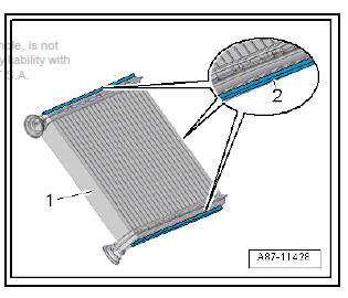
- Check the foam seals -2- attached to the heat exchanger -1- for damage and replace if necessary.
Note
- The foam seal may curl up on insertion if not correctly bonded on.
- Cold air may flow past the heat exchanger if the foam seal is damaged or not properly fitted.
- The illustration shows the heat exchanger for a "Valeo" heater and air conditioning unit.
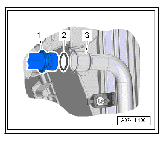
- Check connection -3- of the heat exchanger and the connection of the coolant pipes -1- for damage or dirt.
- Clean and smooth sealing surface for O-ring.
- Moisten the new O-ring -1- with coolant (or lubricate lightly with silicone grease) and attach to the coolant pipe.
- Carefully slide home the heat exchanger in the air conditioning unit.
Note On inserting the heat exchanger, take care not to damage the connections and coolant pipes.
- Slide coolant pipes into heat exchanger as far as stop.
| Caution Risk of leaks at heat exchanger.
|
- Position the heat exchanger holder -3- at the air distribution housing and tighten the bolt -4- to torque (tightening torque: 2 Nm).
- Fit new screw-type clamps -2- at the coolant pipe/heat exchanger joint.
- Tighten bolt -1-.
- Check that screw-type clips are seated correctly on connections of heat exchanger and coolant pipes. They must not make contact with air distribution housing or other components.
- Fill coolant.
 Removing and fitting fresh air blower
control unit - J126-
Removal:
Turn off the ignition and all electricity consumers.
Vehicles without access and start authorisation system
Remove ignition key, if fitted.
Vehicles with access and start author ...
 Removing and installing coolant pipes
on heat exchanger
Removing and installing coolant pipes at
heat exchanger (Valeo)
Note
There are different designs and makes of heater and air conditioning
unit. The individual components of the various heaters and ...
See also:
Tow-starting
The use of jump leads is preferable to tow-starting.
We recommend that you do not tow-start your vehicle. Jump-starting
is preferable.
However, if your vehicle has to be tow-started:
– Engage th ...
