Seat Leon >> Assembly overview - brake servo/brake master cylinder
SEAT Leon Service and Repair Manual / Brake system / Brakes - hydraulics / Brake servo / Master brake cylinder / Assembly overview - brake servo/brake
master cylinder
Assembly overview - brake servo/brake master cylinder, LHD
Note The master brake cylinder and the servo brake can be replaced independently.
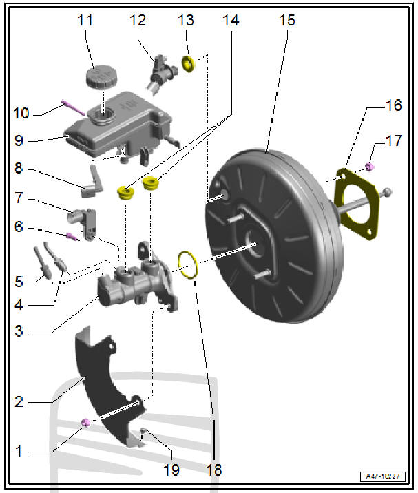
- - Nut
- Replace after each removal
- 23 Nm
- - Heat shield
- Optional equipment
- - Brake master cylinder
- Cannot be repaired
- If defective renew complete unit
- - Brake pipe
- Master brake cylinder / pressure-rod piston circuit to hydraulic unit
- 14 Nm
- - Brake pipe
- From secondary piston circuit of brake master cylinder to hydraulic unit.
- 14 Nm
- - Bolt
- 8 Nm
- - Brake light switch - F-
- - Warning contact for the
brake fluid level - F34-
- Installation locations of the components
- - Brake fluid reservoir
- - Lock pin or studs
- For securing brake fluid reservoir.
- Lead through the brake fluid reservoir and the brake master cylinder
- The lock pin must penetrate into the lug of the brake fluid reservoir.
- 5 Nm
- - Sealing cap
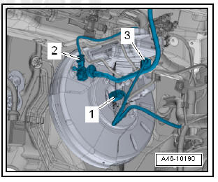
- - Vacuum hose
- With retention valve
- Insert into brake booster
- The brake servo pressure sensor - G294- is fitted only in vehicles with petrol engines.
- - Seal
- Vacuum hose/brake booster
- - Plug
- Moisten with brake fluid and press into brake fluid reservoir
- - Brake servo unit
- Functional check:
- With engine switched off, press brake pedal firmly several times to dissipate vacuum in servo unit
- Now step on and hold brake pedal with medium pressure and start engine. If the brake servo is operating properly, you can clearly feel that the brake pedal begins to sag (the transfer effect is beginning)
- Functional check:
- - Seal
- Renew
- Bonded (only when originally assembled at factory).
- There is no need to replace the cement bond on the brake force booster and on the bulkhead panel.
- - Nut
- 2 off
- Replace after each removal
- Bolting sequence.
- 25 Nm
- - Seal
- Replace if damaged
- Ensure that seals are correctly seated
- Brake master cylinder/brake servo
- - Rubber buffer
Assembly sequence:
- Tighten the screws to 25 Nm in the sequence-3, 4-.
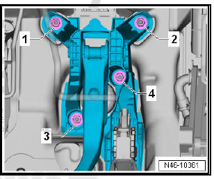
Installation locations of the components:
- - Brake pedal switch - F63-
- - Brake servo pressure sensor - G294-
The brake servo pressure sensor - G294- is fitted only in vehicles with petrol engines.
- - Warning contact for the brake fluid level - F34-
Assembly overview - brake servo/brake master cylinder, RHD
Note The master brake cylinder and the servo brake can be replaced independently.
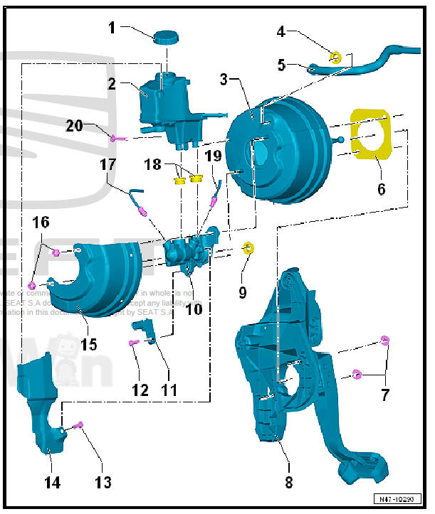
- - Sealing cap
- - Brake fluid reservoir
- With brake fluid level warning contact - F34-
- - Brake servo unit
- Functional check:
- With engine switched off, depress brake pedal firmly several times (to exhaust vacuum in unit).
- Now step on and hold brake pedal with medium pressure and start engine. If the brake servo is functioning properly, the brake pedal will be felt to go down as the servo takes effect.
- Replace completely in the event of a fault (before doing so, check brake servo vacuum system)
- Functional check:
- - Seal
- Vacuum hose/brake booster
- - Vacuum line
- - Seal
- Replace after disassembly
- Bonded (only when originally assembled at factory).
- Remove adhesive residue
- There is no need to replace the cement bond on the brake force booster and on the bulkhead panel.
- - Nut
- 2 off
- 20 Nm
- - Mounting bracket with brake pedal
- - Seal
- Replace if damaged
- Ensure that seals are correctly seated
- Brake master cylinder/brake servo
- - Brake master cylinder
- When attaching brake master cylinder to brake servo, make sure plunger rod is properly positioned in brake master cylinder.
- - Brake light switch - F-
- - Bolt
- 8 Nm
- - Bolt
- 8 Nm
- - Heat shield
- On brake fluid reservoir.
- - Heat shield
- For brake servo.
- - Nut
- Replace after disassembly
- 2 off
- Self-locking
- 23 Nm
- - Brake pipe
- From secondary piston circuit of brake master cylinder to hydraulic unit.
- 14 Nm
- - Seal cap
- Replace if damaged
- Ensure that seals are correctly seated
- Moisten sealing plugs with brake fluid before pressing brake fluid reservoir into brake master cylinder
- Between brake master cylinder and brake fluid reservoir
- - Brake pipe
- Master brake cylinder / pressure-rod piston circuit to hydraulic unit
- 14 Nm
- - Lock pin or studs
- For securing brake fluid reservoir.
- Lead through the brake fluid reservoir and the brake master cylinder
- The lock pin must penetrate into the lug of the brake fluid reservoir.
- 5 Nm

 Removing and installing brake servo
Removing and installing brake servo,
LHD
Note
If there are problems with the brake servo, first check the brake
servo vacuum system
Special tools and workshop equipment required
Release tool ...
See also:
Changing a wheel
Change the wheel as described below
– Pull off the hub cap. See fig. 154.
– Slacken the wheel bolts
– Raise the car with the jack in the corresponding zone
– Take off the wheel and t ...
