Seat Leon >> Separating control unit from hydraulic unit
Special tools and workshop equipment required
- Torque screwdriver - VAG 1624-
- ESD workplace - VAS 6613-
- Torx socket T25
| Caution The ABS control unit - J104- and the ABS hydraulic unit - N55- must be removed before they are separated. |
- If a control unit is defective, separate the control unit from the hydraulic unit and renew only the control unit.
- If the hydraulic unit is defective, the hydraulic unit must be renewed together with the control unit.
Note
- Before removing the control unit, read out the event memory and print out the fault code if applicable.
- The ESP unit must be removed in order to separate the control unit from the hydraulic unit.
- The ESP unit may only be removed by suitably qualified personnel.
- The control unit and hydraulic unit may only be separated by suitably qualified personnel.
WARNING
|
Removing
The ABS hydraulic unit - N55- must be removed along with the ABS control unit - J104-
| Caution The electrical components of the printed circuit can be damaged by static loading. Before working on electric components, touch an earthed object, ESD workplace - VAS 6613- . Do not directly touch connector contacts or electronic components. |
- Set down hydraulic unit with control unit on ESD work station - VAS 6613- .
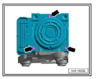
- Unscrew the 3 Torx bolts -arrows- of the control unit and discard immediately.
- Place the hydraulic unit with the control unit facing upwards on the ESD workplace - VAS 6613- .
- Remove the control unit from the hydraulic unit without tilting it.
- Cover the control unit solenoids with a lint-free cloth.
- Check cleanliness of hydraulic unit sealing surface; clean with methylated spirits and a lint-free cloth if necessary.
Note
- Discard the old bolts immediately.
- Never re-use old bolts.
Note
- Make sure the valve coils do not catch; otherwise they can be distorted by the retainer.
- The seal on the control unit cannot be replaced.
- The seal on the control unit must not be lifted or pulled out.
| Caution Cover the open hydraulic unit. Protect the hydraulic unit, sealing surfaces, valve body and pressure sensor against dirt and damage. Do not apply battery voltage to check the pump motor; this can cause scorching on the contacts. Protect the contact surfaces of the pressure sensor against mechanical damage and electrostatic discharge. |
Instructions for replacing the ABS hydraulic unit - J104-
Note
- Only the ABS control unit may be renewed separately - J104- .
- It is permissible to fit a new ABS control unit - J104- to the existing hydraulic unit.
- It is not permissible to fit the existing ABS control unit - J104- to a new hydraulic unit.
- If the ABS hydraulic unit - N55- is defective, it must always be renewed together with the ABS control unit - J104- .
Elements of the ABS control unit - J104-
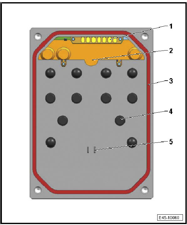
- - Pressure sensor contact
- Never touch the contacts
- Some versions may differ from this illustration
- - Pressure sensor
- The pressure sensor must not be modified or damaged
- The pressure sensor cannot be replaced
- Some versions may differ from this illustration
- - Seal
- The seal on the control unit must not be lifted or pulled out
- The seal on the control unit cannot be replaced
- - Contact pins
- The contact pins must not be damaged or bent
- Never apply tools to the contact pins
- - Contact for pump motor
- The contact must not be damaged or bent
You should replace the control unit:
- If clear faults are determined in the control unit using the vehicle diagnosis device "defective control unit".
- If there is visible damage to the control unit housing or connector.
Replacement of control units:
The control unit may only be replaced by suitably qualified personnel.
Use only the new components specified in the repair kit.
Always use new bolts for attaching the control unit to the hydraulic unit.
The seal on the control unit must not be lifted or pulled out.
The seal on the control unit cannot be replaced.
Do not blow out the control unit or hydraulic unit with compressed air.
The valve coils in the control unit cannot be re-adjusted.
The valve coils in the control unit cannot be replaced.
The pressure sensor must not be modified or damaged.
The pressure sensor cannot be replaced
Never subject the sensor housing to mechanical load.
Never take measurements at the contact points in the control unit.
Never take measurements at the contact points in the hydraulic unit.
The contact pins in the hydraulic unit must not be damaged or bent.
The contacts cannot be replaced.
The use of contact sprays on the contacts and pressure sensor is not permissible.
There must not be any foreign matter between the control unit and hydraulic unit.
 Connecting brake lines to hydraulic unit
Connecting brake lines to hydraulic unit,
LHD
On the tandem master cylinder:
- Primary piston circuit of brake master cylinder to hydraulic unit.
Markings: Ø 6 mm and union nut with short th ...
 Fitting control unit to hydraulic unit
Special tools and workshop equipment required
Torque screwdriver - VAG 1624-
ESD workplace - VAS 6613-
Torx socket T25
Clean sealing surface on hydraulic unit -2- using pla ...
See also:
Lane change assist
Overview - lane change assist
- Front camera for driver assist
systems - R242-
Removal and installation
- Windscreen heater for sensors,
front - Z113-
Installation location: in ...
