Seat Leon >> Assembly overview - drive shaft
SEAT Leon Service and Repair Manual / Running gear, axles, steering / Front suspension / Drive shaft / Assembly overview - drive shaft
Assembly overview - drive shaft, constant velocity joint VL100
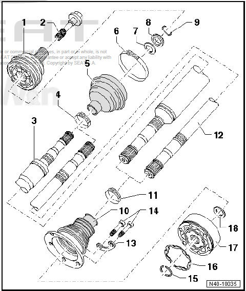
- - Outer constant velocity joint
- Always replace completely
- Removing
- Installing: drive onto shaft as far as stop using plastic hammer
- Checking
- - Bolt
- Always renew after removing
- Loosening and tightening
- 200 Nm +180º
- - Right hand drive shaft
- - Clamp
- Always renew after removing
- Tightening
- - Dust guard
- Check for splits and chafing
- Material: Hytrel (Polyelastomer)
- - Clamp
- Always renew after removing
- Tightening
- - Dished spring
- Installation position
- Corresponding to - Electronic parts catalogue"ETKA"
- - Thrust washer
- Installation position
- Corresponding to - Electronic parts catalogue"ETKA"
- - Securing ring
- Always renew after removing
- Insert in groove in shaft
- - Dustguard for constant velocity joint
- Material: Hytrel (Polyelastomer)
- Without breather hole
- Check for splits and chafing
- Drive off constant velocity joint with a drift
- Coat sealing surface of constant velocity joint with -D 454 300 A2- before installing.
- - Clamp
- Always renew after removing
- Tightening
- - Left hand drive shaft
- - Locking plate
- - Internal splined bolt
- M8 x 48
- Always renew after removing
- Pre-tighten diagonally to 10 Nm and then tighten completely diagonally to the respective tightening torque.
- 40 Nm
- - Securing ring
- Remove and install using circlip pliers - VW 161 A-
- - Seal
- The surface that is attached to the constant velocity joint should be free of grease and oil
- - Inner constant velocity joint
- Always replace completely
- Pressing off
- Insertion
- Checking
- - Dished spring
- Installation position
Assembly overview - drive shaft, constant velocity joint VL107
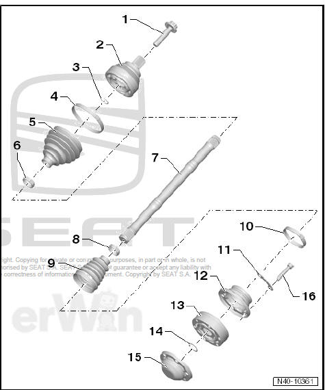
- - Bolt
- Always renew after removing
- Loosening and tightening
- Before securing, clean the threads in the CV joint using a thread tap
- 200 Nm +180º
- - Outer constant velocity joint
- Always replace completely
- Removing
- Installing: drive onto shaft as far as stop using plastic hammer
- Checking
- - Securing ring
- Always renew after removing
- Insert in groove in shaft
- - Clamp
- Always renew after removing
- Tightening
- - Dust guard
- Check for splits and chafing
- Material: Hytrel (Polyelastomer)
- - Clamp
- Always renew after removing
- Tightening
- - Drive shaft
- - Clamp
- Always renew after removing
- Tightening
- - Dustguard for constant velocity joint
- Material: Hytrel (Polyelastomer)
- Without breather hole
- Check for splits and chafing
- Drive off constant velocity joint with a drift
- Coat sealing surface of constant velocity joint with -D 454 300 A2- before installing.
- - Clamp
- Always renew after removing
- Tightening
- - Locking plate
- - Cover
- Drive off carefully with drift
- Coat sealing surface of constant velocity joint with -D 454 300 A2- before installing.
- Adhesive surface must be free of oil and grease!
- - Inner constant velocity joint
- Always replace completely
- Pressing off
- Insertion
- Checking
- - Securing ring
- Remove and install with circlip pliers - VW 161 A-
- - Cover
- Always renew after removing
- Always renew
- Pressing off
- - Internal splined bolt
- Always renew after removing
- M10 x 52
- Pre-tighten diagonally to 10 Nm and then tighten completely diagonally to the respective tightening torque.
- 70 Nm
Assembly overview - drive shaft, triple roller joint AAR3300i
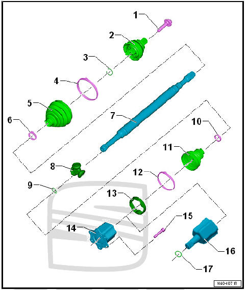
- - Bolt
- Always renew after removing
- Loosening and tightening
- Before securing, clean the threads in the CV joint using a thread tap
- 200 Nm +180º
- - Outer constant velocity joint
- Always replace completely
- Removing
- Installing: drive onto shaft with plastic hammer until compressed circlip seats
- Checking
- - Securing ring
- Always renew after removing
- Insert in groove in shaft
- - Clamp
- Always renew after removing
- Tightening
- - Dustguard for constant velocity
joint
- Check for splits and chafing
- Material: Hytrel (Polyelastomer)
- - Clamp
- Always renew after removing
- Tightening
- - Drive shaft
- - Triple roller star with rollers
The chamfer -arrow- points towards drive shaft splines.- Removing
- - Securing ring
- Always renew after removing
- Insert in groove in shaft
- - Clamp
- Always renew after removing
- Tightening
- - Dustguard for tripod type joint
- Check for splits and chafing
- - Clamp
- Always renew after removing
- Tightening
- - Adapter
- - Joint body
- Removing
- - Internal splined bolt
- M10 x 23
- Pre-tighten diagonally to 10 Nm and then tighten completely diagonally to the respective tightening torque.
- 70 Nm
- - Joint body
- Removing
- - Securing ring
- Always renew after removing
- Insert in groove in shaft
 Drive shaft
Overview - drive shaft
Differing characteristics of the drive shafts when fitted.
...
 Removing and installing drive shaft
Removing and installing drive shaft, left
drive shaft, constant velocity joints
VL100 and VL107
Special tools and workshop equipment required
Torque wrenches - V.A.G 1332-
Puller - T105 ...
See also:
Removing and installing ABS control
unit - J104- / ABS hydraulic unit - N55-
Removing and installing ABS control
unit - J104- / ABS hydraulic unit - N55- ,
left hand steering
Special tools and workshop
equipment required
Torque wrenches -
V.A.G 1331-
Torque w ...
