Seat Leon >> Repairing subframe
SEAT Leon Service and Repair Manual / Running gear, axles, steering / Front suspension / Sub-frame / Repairing subframe
Special tools and workshop equipment required
- attachment tool - T10205-
- Torque wrenches - V.A.G 1332-
- Hydraulic press - VAS 6178-
- Foot pump - VAS 6179-
- attachment tool - VAS 6779-
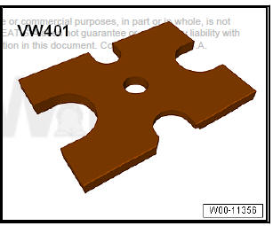
- Tightening plate - VW 401-
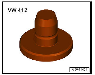
- Die - VW 412-
Renewing bonded rubber bushes for pendulum support
- If fitted, remove front noise insulation.
- Remove hexagon nut -1- from coupling rod -3- (left and right sides).
- Pull out coupling rod -3- from anti-roll bar -2- on left and right side.
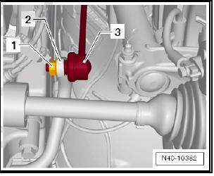
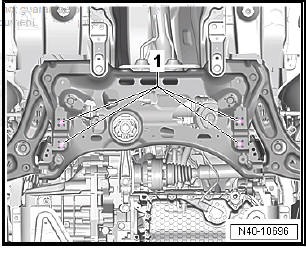
- Remove bolts -1- for anti-roll bar.
- Leave the anti-roll bar in its installation position in the vehicle.
- Remove pendulum support.
Pressing out bonded rubber bush
- Attach assembly tool - VAS 6779- to subframe as shown in illustration.
- Place thrust piece for removal - VAS 6779-1- -1- on bonded rubber bush so that flattened side -arrow- faces to direction of travel.
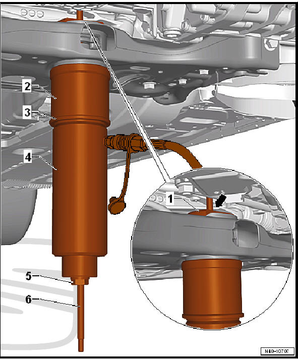
- - Thrust piece for removal - VAS 6779-1-
- - Pipe - VAS 6779-4-
- - Pressure element - VAS 6779-5-
- - Hydraulic press - VAS 6178- and thrust piece - T10205/13-
- - Hexagonal nut - VAS 6779-3-
- - Threaded spindle - VAS 6779-2-
- Press out both bonded rubber bushes until upper bonded rubber bush -2- is visible in pendulum support opening -arrow- in subframe.
- Visually inspect outer ring of upper bonded rubber bush -2-.
- If outer ring of upper bonded rubber bush -2- is deformed, destroy it through opening of pendulum support -arrow- in pendulum support.
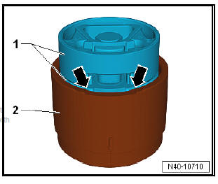
- Using a chisel or similar tool -1-, break out an opening in outer ring of upper bonded rubber bush -2-.
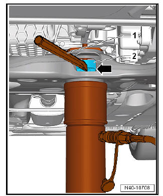
Note This step is necessary to prevent the outer ring of the upper bonded rubber bush from tilting sideways and catching in the aperture for the pendulum support in the subframe.
- Press out bonded rubber bushes completely (both bushes are pressed out together).
Preparing bonded rubber bushes for installation
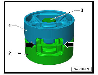
- Place both bonded rubber bushes -1- and -2- together so that the cut-outs -arrows- line up precisely.
- Bolt bonded rubber bushes -1- and -2- hand-tight together using original bolt -3-.
- Insert bonded rubber bushes -1- into larger diameter of funnel - VAS 6779/6- -2- (with bolt head pointing upwards).
- Align bonded rubber bushes -1- in tube - VAS 6779/6- -2-. The cut-out in the bonded rubber bush must align exactly with the recess -arrow- in the tube - VAS 6779/6- -2-.
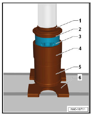
- Press in bonded rubber bush -3- in tube - VAS 6779/6- to stop, as illustrated.
- Die - VW 412-
- Thrust piece - VAS 6779-5- (side marked "A" faces upwards)
- Bonded rubber bush
- Cone - VAS 6779-6-
- Pipe - VAS 6779-4-
- Tightening plate - VW 401-
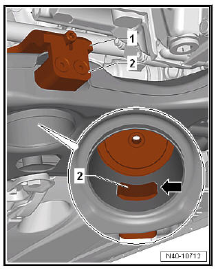
- Insert counterhold - VAS 6779-7- -1- into subframe.
- Insert insert - VAS 6779/7-1A- -2- into pendulum support opening in subframe.
- Bolt insert - VAS 6779/7-1A- to counterhold - VAS 6779/7- -1-.
- Ensure that the insert - VAS 6779/7-1A- -2- is correctly seated in the pendulum support opening of the subframe -arrow-.
Insert the bonded rubber bush
- Screw threaded spindle - VAS 6779/2- -7- into counterhold - VAS 6779/7- -1-
- Attach assembly tool - VAS 6779- to subframe as shown in illustration.
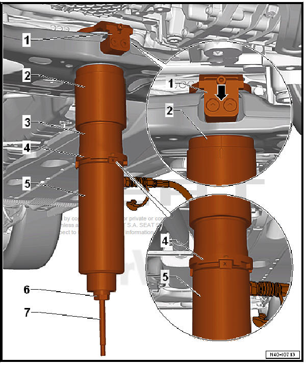
- - Retainer (Counterhold) - VAS 6779/7-
- - Cone - VAS 6779/6- , -arrow marking- on the cone must be in the middle opposite the two screws -arrow-
- - Thrust piece - VAS 6779/9-
- - Stepped ring - VAS 6779/8- . The mark -I- on stepped ring must align with mark -X- on thrust piece - VAS 6779/9-
- - Hydraulic press - VAS 6178- and thrust piece - T10205/13-
- - Hexagonal nut - VAS 6779/3-
- - Threaded spindle - VAS 6779/2-
- Press in both bonded rubber bushes together.
- Detach assembly tool - VAS 6779- from subframe and check that pressed-in bonded rubber bushes are seated correctly.
- Bolt anti-roll bar to subframe and coupling rods.
- Install pendulum support .
- Install front noise insulation .
Specified torques
- Bolts for pendulum support.
- Bolts for noise insulation .
 Removing and installing subframe with
steering box
Removing and installing subframe with
steering box
Removing and installing subframe with
steering box, LHD
Special tools and workshop equipment required
Ball joint puller - T10187-
Torque wrenches - V.A.G 1332-
Removing
To preve ...
 Removing and installing anti-roll bar
Special tools and workshop equipment required
Torque wrenches - V.A.G 1332-
Engine elevator - V.A.G 1383 A-
Removing
Remove front wheels.
If present, remove lower noise insulati ...
See also:
Removing and installing lock carrier
Special tools and workshop equipment required
Counterhold - T10038-
Centre guide - T10093-
Release lever - U30800-
Torque wrench - V.A.G 1331-
Release lever - 80 20 ...
